Switching Facility for Crossed Paths

a technology of crossing facility and crossing path, which is applied in the direction of transportation and packaging, rope railways, roads, etc., can solve the problems of increasing the cost of the facility, increasing the difficulty of ensuring stable travel of the article transport vehicle, and increasing the difficulty of smooth operation

Active Publication Date: 2010-09-30
DAIFUKU CO LTD
View PDF14 Cites 30 Cited by
  • Summary
  • Abstract
  • Description
  • Claims
  • Application Information

AI Technical Summary

Benefits of technology

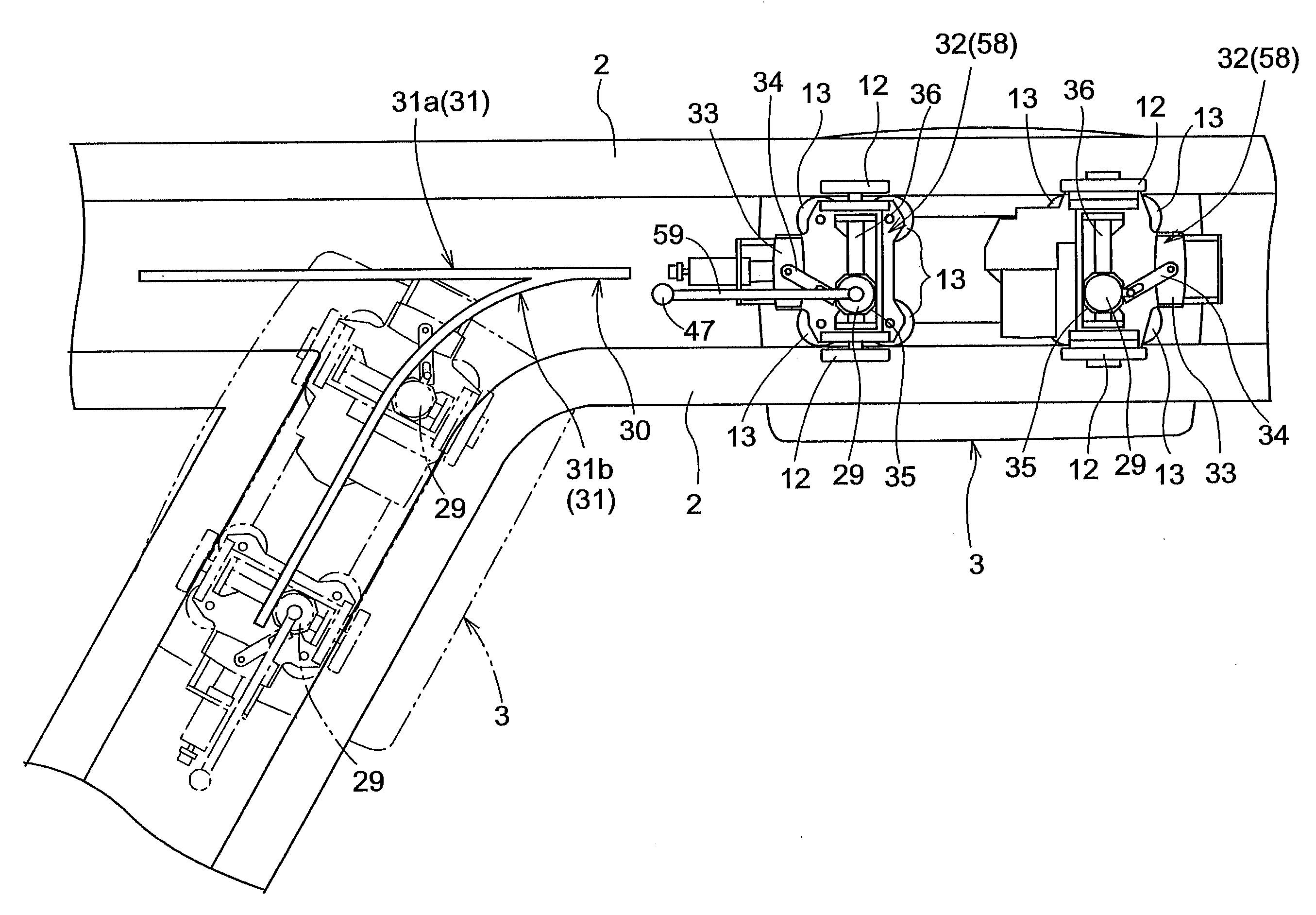
[0017]Accordingly, a switching facility for crossed paths is provided, which allows the article transport vehicles to pass the crossing area smoothly either along the first path or the second path without causing the configuration to become complex.

Problems solved by technology

This tends to make the facility more complex because of, among other things, the wiring work for supplying electric power to the switching actuator, and because of the need to secure installation space for the switching actuator.
And, in the facility which has a number of crossing portions, the switching actuator needs to be provided in each of the plurality of crossing portions, which tends to raise the cost of the facility.
This makes it more difficult to ensure stable travel of the article transport vehicle and smooth passage of the article transport vehicle through the crossing portion.
And, since the rotatable travel rail is switched between the first travel position and the second travel position as the article transport vehicle advances into the crossing portion, a crossing portion requires both a first rotation operation means and a second rotation operation means, leading to a larger installation space and a more complex configuration of the facility.
In this case, in order to switch the rotatable guide rail between the first guiding position and the second guiding position as the article transport vehicle advances into the crossing portion, two additional operation means must be installed in the crossing portion in addition to the first rotation operation means and the second rotation operation means, leading to a more complex configuration of the facility.

Method used


Image

  • Switching Facility for Crossed Paths
  • Switching Facility for Crossed Paths
  • Switching Facility for Crossed Paths

Examples


Embodiment Construction

[0027]An embodiment of an article transport facility is described with reference to the attached drawings.

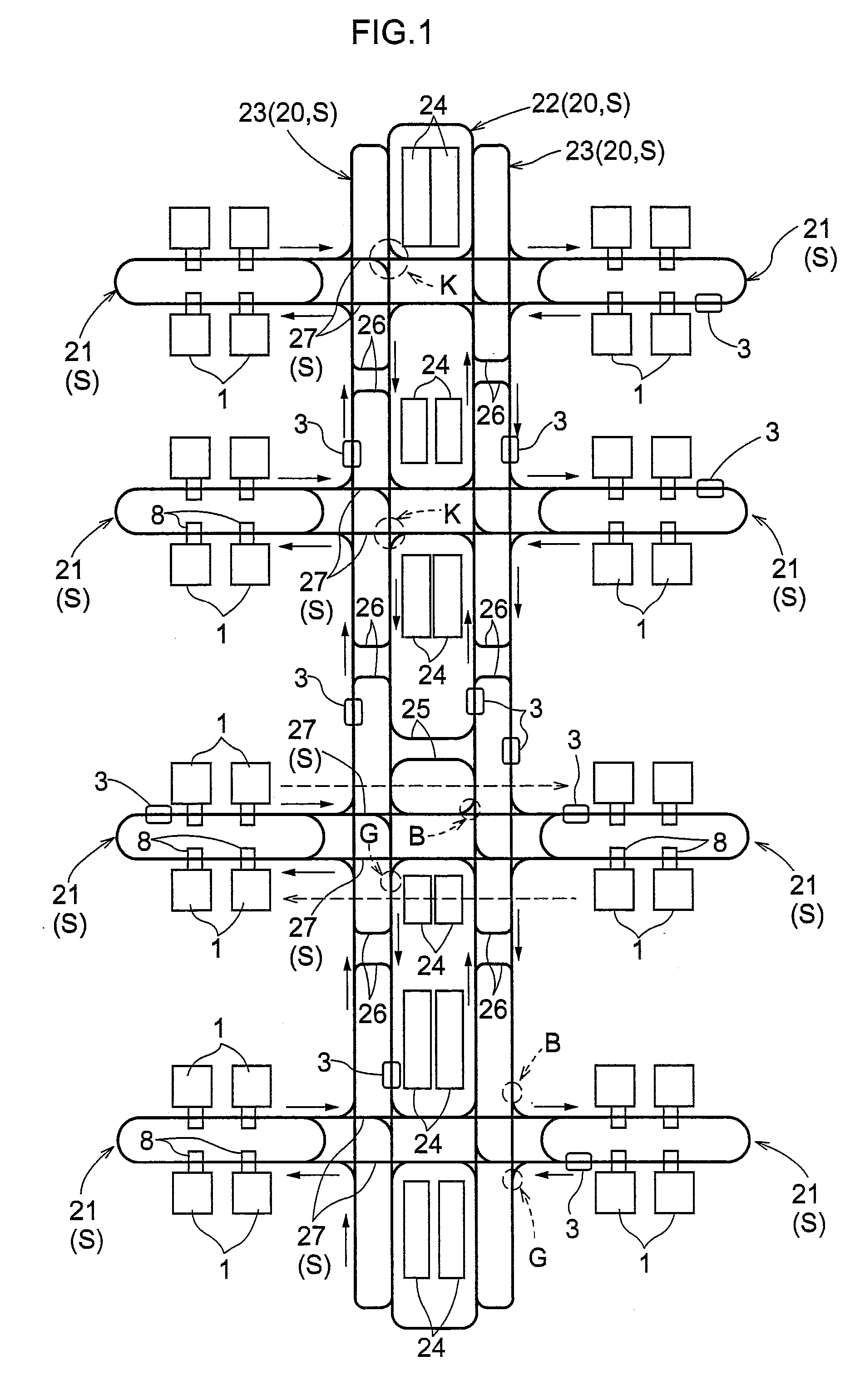
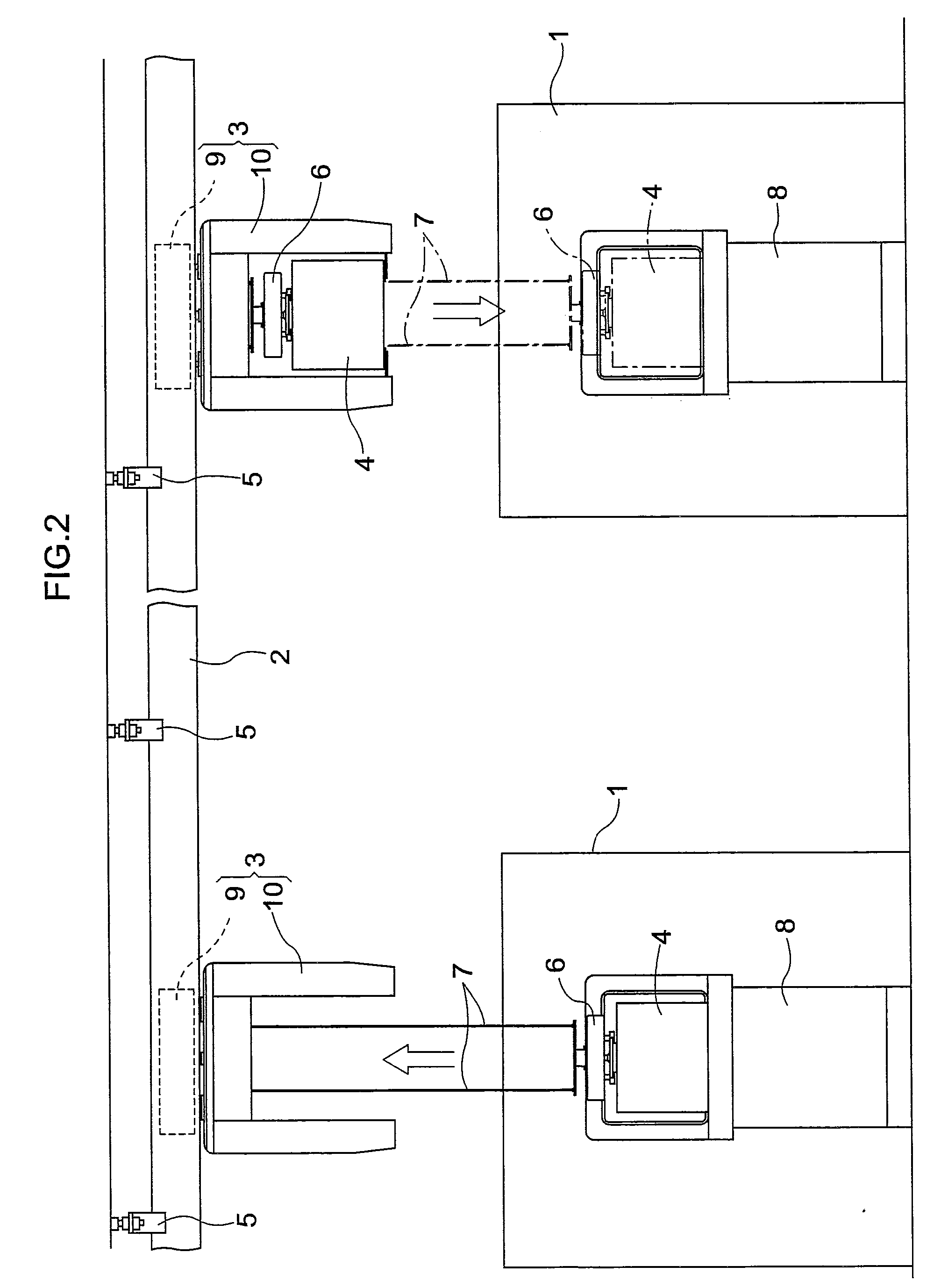
[0028]As shown in FIG. 1, the present article transport facility is provided with a plurality of article processors 1 for processing semiconductor substrates. Rails 2 are installed on the ceiling side, or to the ceiling, such that each of the rail 2 extends along and passes by these article processors 1 to form a travel path S. A plurality of article transport vehicles 3, of the type that is suspended from the ceiling and which can travel in one direction along a travel path S, are provided. The article transport facility is configured such that the article transport vehicles 3 transport the articles 4 (i.e. containers for storing semiconductor substrates) among the plurality of article processors 1. Each rail 2 for the vehicles to travel on (travel rail for short) is fixedly installed to the ceiling with rail brackets 5 (see FIG. 2).

[0029]As shown in FIG. 2, each article transp...


PUM


Abstract

A path switching facility for crossed paths comprises: at least one article transport vehicle configured to travel along a first path and a second path that crosses the first path; a guide rail for guiding a guided roller of the article transport vehicle; a travel rail for guiding and supporting travel wheels of the article transport vehicle; a rotatable guide rail and a rotatable travel rail both located in a crossing area; a push operating portion provided to the article transport vehicle to push one of the rotatable guide rail and the rotatable travel rail; and, an operatively connecting device for coupling a rotation of the rotatable guide rail with a rotation of the rotatable travel rail.

Description

BACKGROUND OF THE INVENTION[0001]1. Field of the Invention[0002]The present invention relates to a switching facility for crossed paths provided in a crossing area where the first path and the second path cross each other for switching between a first switching state in which an article transport vehicle is caused to pass through the crossing area along the first path and a second switching state in which the article transport vehicle is caused to pass through the crossing area along the second path.[0003]2. Description of the Related Art[0004]In the switching facility for crossed paths described above, the article transport vehicle can pass through the crossing portion along the first path and the second path by switching the switching means to the first switching state when the article transport vehicle passes through the crossing portion along the first path, and by switching the switching means to the second switching state when the article transport vehicle passes through the c...

Claims


Application Information

Patent Timeline
Patent Type & Authority Applications(United States)
IPC IPC(8): E01B7/00
CPCH01L21/67715H01L21/67736H01L21/67733B65G37/02H01L21/6773H01L21/67769B65G2201/0297
Inventor OGURO, KEISUKEFUJITA, MOTOHIROTAKEMOTO, YUUYA
Owner DAIFUKU CO LTD
Why Eureka
Try Eureka