[0006]The object of the present invention is to provide an arrangement and a method whereby the internal surfaces of an EGR cooler device are kept clean of
soot deposits from the exhaust gases in a simple and effective manner.
[0007]This object is achieved with the arrangement of the invention. Exhaust gases recirculated in a combustion engine are cooled in an EGR cooler device which may comprise one or more EGR coolers before the gases are mixed with
compressed air and led to combustion engine. If the exhaust gases are cooled effectively, they reach at a location within the EGR cooler device a temperature at which the
water vapor in the exhaust gases condenses. Condensate will therefore form from that location in the EGR cooler device to an aperture through which the exhaust gases are led out from the EGR cooler device. The exhaust gases from a combustion engine usually contain a small amount of sulphur. Consequently, the
water vapor which condenses in an EGR cooler device forms a condensate which has a low pH value. This condensate is very suitable for use as a
cleaning agent for removing
soot deposits in an EGR cooler device. The furthest downstream portions of an EGR cooler device in which condensate normally forms during operation of a combustion engine is therefore usually substantially freed of
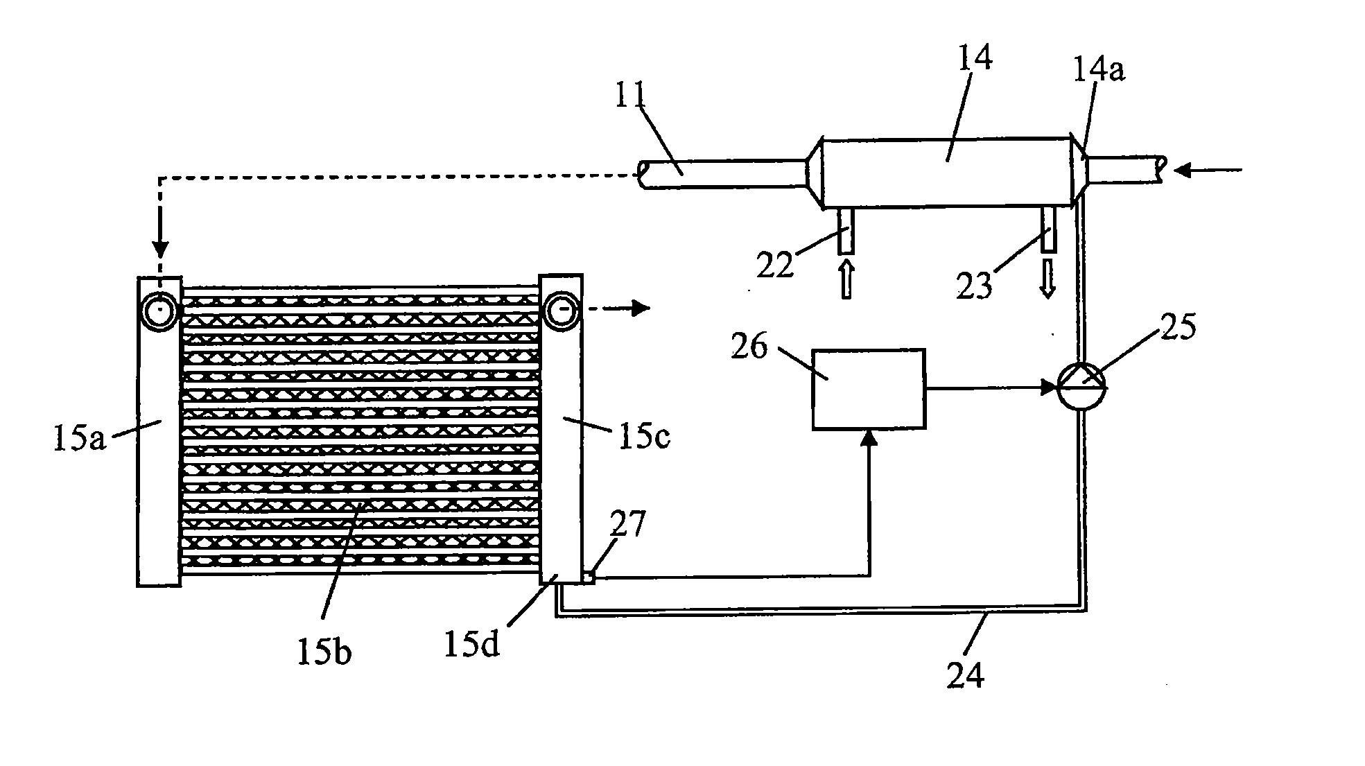
soot deposits. According to the invention, the condensate formed is also used for cleaning other portions of the EGR cooler device. Condensate is thus accumulated in a container device before it is led through a line to a suitable portion of the EGR cooler device where it is led in and mixed with the flowing exhaust gases. The condensate led into the EGR cooler device effectively dissolves the soot deposits on the internal surfaces of the EGR cooler device. The soot deposits released from the walls are carried off out of the EGR cooler device by the exhaust flow. However, the warm exhaust gases relatively quickly vaporise the condensate. This vaporisation results in the exhaust gases undergoing extra cooling in the EGR cooler device. The exhaust gases are thus cooled more quickly in the EGR cooler device in situations where condensate is supplied. The
water vapor in the exhaust gases therefore reaches its
condensation temperature relatively quickly and condensate forms at a location further upstream in the EGR cooler device. Supplying a suitable amount of condensate will make it possible for substantially all of the internal surfaces of the EGR cooler device which are situated downstream of the location where condensate is added to be coated with condensate and cleaned of soot deposits.
[0008]According to a preferred embodiment of the present invention, said flow section for the exhaust gases where condensate is led into the EGR cooler device is situated close to an inlet section for the exhaust gases in the EGR cooler device. This means that substantially all of the internal surfaces of the EGR cooler device can at least for a short time be coated with condensate and cleaned of soot deposits. Said container device is with
advantage situated close to an outlet section for the exhaust gases in the EGR cooler device. Condensate forms most abundantly at the end of the EGR cooler device and can be gathered substantially directly in a container device which is so positioned. Condensate which forms earlier in the EGR cooler device is carried by the exhaust flow to the outlet section and accumulates there. In cases where the EGR cooler device comprises an air-cooled EGR cooler with a conventional configuration, the condensate may thus accumulate on a bottom portion of an outlet tank of the EGR cooler.
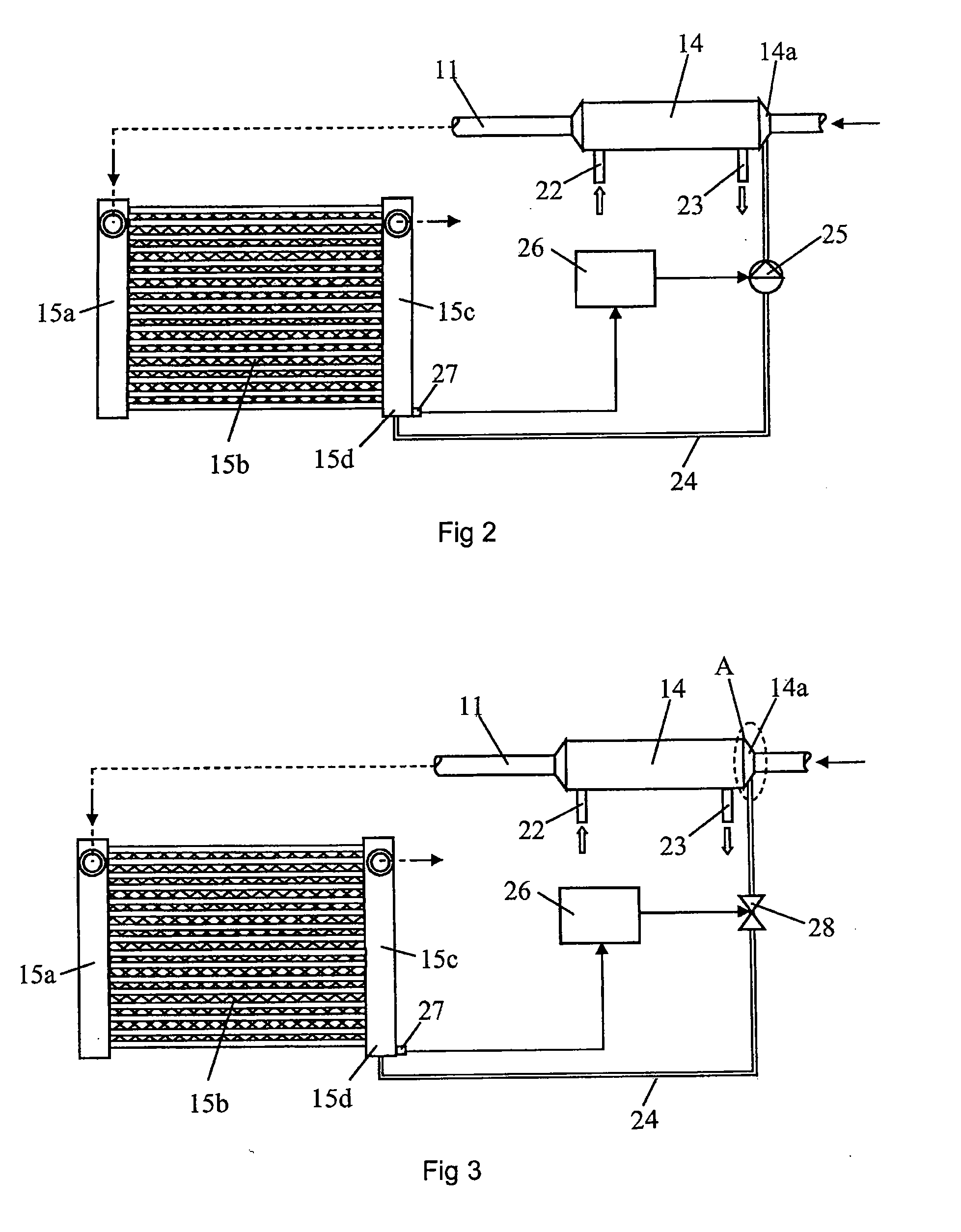
[0009]According to another preferred embodiment of the present invention, said driving means comprises a pump adapted to being activated when condensate is to be supplied to the EGR cooler device. With a pump arranged at a suitable location in the line, condensate can be supplied to the EGR cooler device on desired occasions and in a desired amount. Condensate may be supplied substantially continuously during operation of the combustion engine or at specified intervals. Alternatively, the pressure drop or cooling of the exhaust gases passing through the EGR cooler device may be detected. A large pressure drop or little cooling of the exhaust gases passing through the EGR cooler device will indicate that it may need cleaning. Alternatively, said driving means may involve said flow section for the exhaust gases in the EGR cooler device where condensate is led into the EGR cooler device being so configured that it narrows locally relative to adjacent flow sections. The exhaust gases which flow through the narrowing flow section will thus assume a greater velocity, thereby reducing the stationary pressure in that section. Condensate can thereby be drawn from the gathering container, through a line and into said section. The line comprises with
advantage a valve by which the flow of condensate to the EGR cooler device is regulated. Condensate can therefore be supplied on desired occasions and in desired amounts. The arrangement comprises preferably a
control unit adapted to controlling said driving means so that condensate is supplied on desired occasions and in a desired amount. Such a
control unit, which may be a computer unit with suitable
software, makes it possible for the EGR cooler device to be cleaned with condensate in such a way that the whole EGR cooler device's internal surfaces which are in contact with the exhaust gases are kept substantially free from soot deposits. The capacity of the EGR cooler device is thus maintained substantially unchanged during operation of combustion engine.
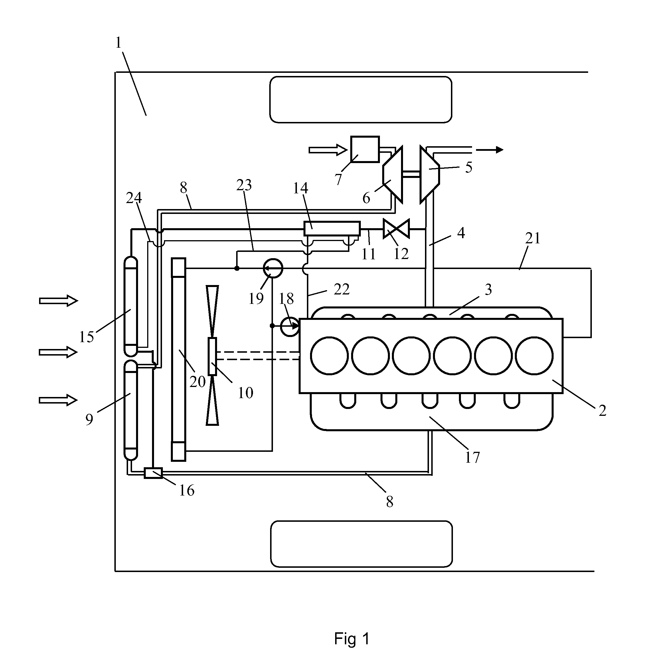
[0010]According to a preferred embodiment of the present invention, the EGR cooler device comprises a first EGR cooler adapted to subjecting the exhaust gases to a first step of cooling, and a second EGR cooler adapted to subjecting the exhaust gases to a second step of cooling. Cooling the exhaust gases from a temperature of about 500-600° C. to a temperature close to that of the surroundings is facilitated if the exhaust gases are cooled in a number of stages. To this end, the exhaust gases may undergo cooling by a
coolant in the first EGR cooler. The
coolant may take the form of the
coolant of combustion engine's cooling
system. That coolant will certainly be at a relatively high temperature but nevertheless at a definitely lower temperature than the exhaust gases led into the first EGR cooler. The exhaust gases may undergo cooling by air at the temperature of the surroundings in the second EGR cooler. The exhaust gases may thus be subjected to a second step of cooling to a temperature close to that of the surroundings, and to a temperature corresponding to that to which the
compressed air is cooled in a charge air cooler.

