

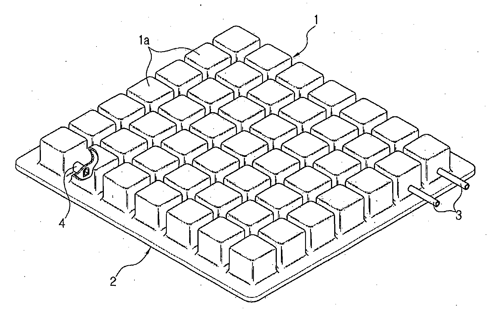
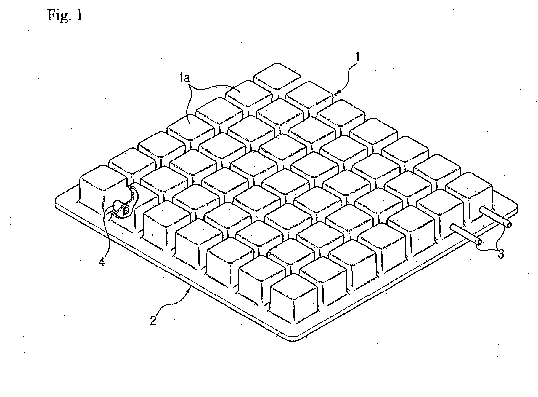
Manufacturing method of air mat
a manufacturing method and air mat technology, applied in the field of air mat manufacturing, can solve the problems of low bonding quality, unfavorable product cost increase, and partially broken, so as to reduce the number of manufacturing processes, prevent unnecessary consumption of materials, and increase bonding force
- Summary
- Abstract
- Description
- Claims
- Application Information
AI Technical Summary
Benefits of technology
Problems solved by technology
Method used
Image

Examples
Embodiment Construction
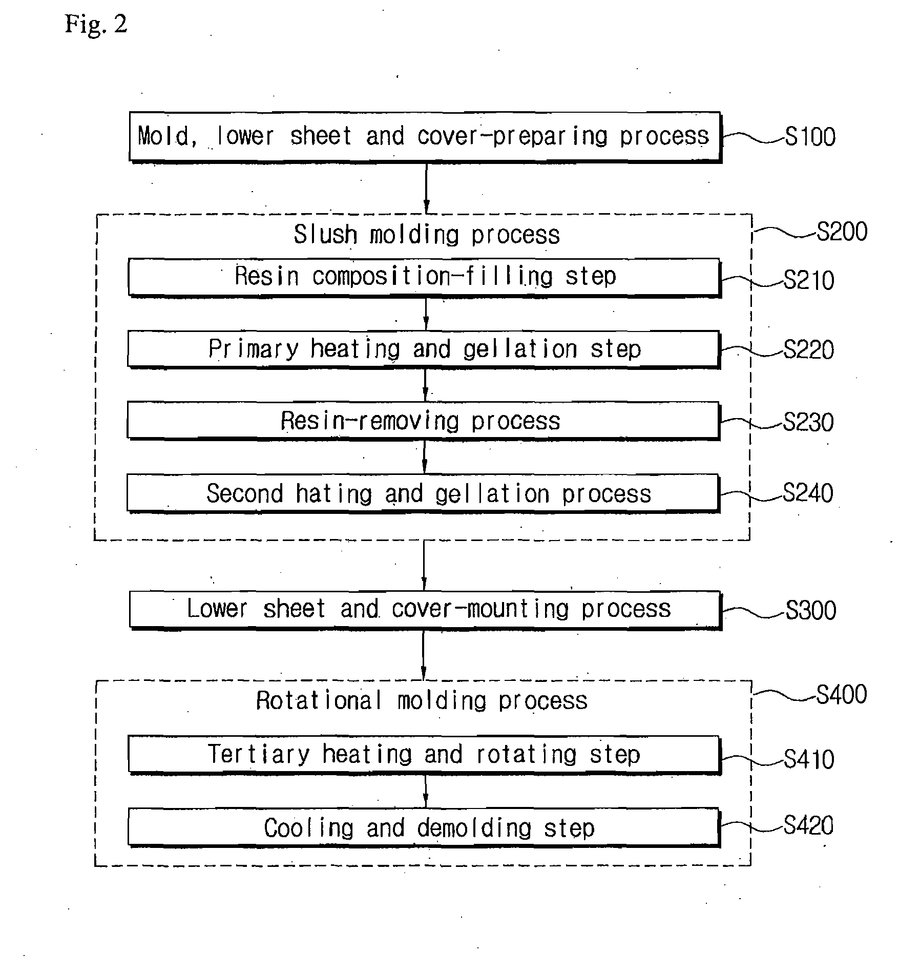
[0060]To accomplish the above-mentioned objects, according to the present invention, as shown in FIG. 2, there is provided a method for manufacturing an air mat basically including the steps of conducting a lower mold and a lower sheet-preparing process S100 by preparing a lower mold and a lower sheet; conducting a slush molding process S200 by molding a cushion part in the prepared lower mold by means of slush molding; conducting a lower sheet and cover-mounting process S300 by mounting the lower sheet and a cover on the lower mold having the cushion part molded therein through the slush molding; and conducting a rotational molding process S400 by bonding the lower sheet mounted on the lower mold and the cushion part by means of rotational molding.
[0061]First, as shown in FIGS. 3a and 3b, the process S100 for preparing the mold and the lower sheet is the step of preparing a lower mold 10 adapted to mold the cushion part of the air mat, a lower sheet 20 adapted to become the bottom ...
PUM
| Property | Measurement | Unit |
|---|---|---|
| temperature | aaaaa | aaaaa |
| temperature | aaaaa | aaaaa |
| temperature | aaaaa | aaaaa |
Abstract
Description
Claims
Application Information