Fluorescence detection system

a fluorescence detection and fluorescence technology, applied in the field of fluorescence detection systems, can solve the problems of increasing the conspicuousness of the abovementioned problem, decreasing the sensitivity of detecting fluorescence,

Active Publication Date: 2010-09-30
NIPPON SHEET GLASS CO LTD
View PDF7 Cites 8 Cited by
  • Summary
  • Abstract
  • Description
  • Claims
  • Application Information

AI Technical Summary

Benefits of technology

[0010]In the present invention, the predetermined fourth wavelength is preferably longer than the predetermined third wavelength by 10 nm or more.

Problems solved by technology

However, a conventional fluorescence analysis device has a problem that excitation light with which a sample is irradiated from a light source leaks into the detector to increase background at the time of detecting fluorescence, decreasing sensitivity of detecting fluorescence.
As a microchemical system has progressed, a sample to be used becomes smaller in amount, so that the abovementioned problem may become more conspicuous.

Method used


Image

  • Fluorescence detection system
  • Fluorescence detection system
  • Fluorescence detection system

Examples


example 1

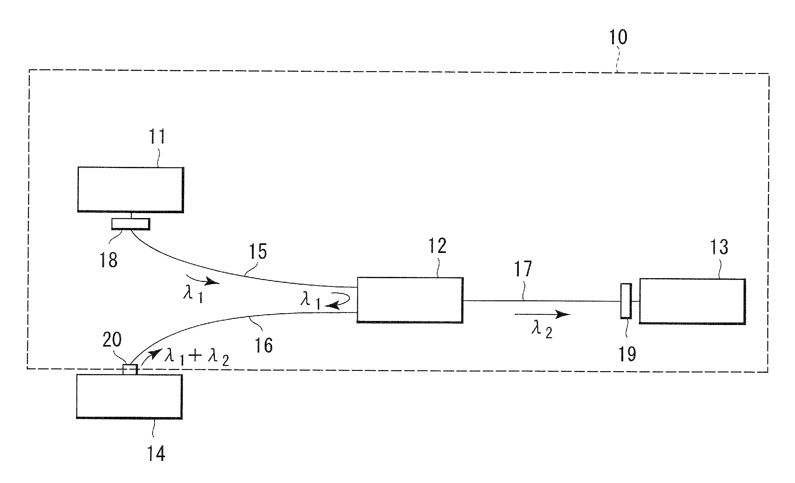
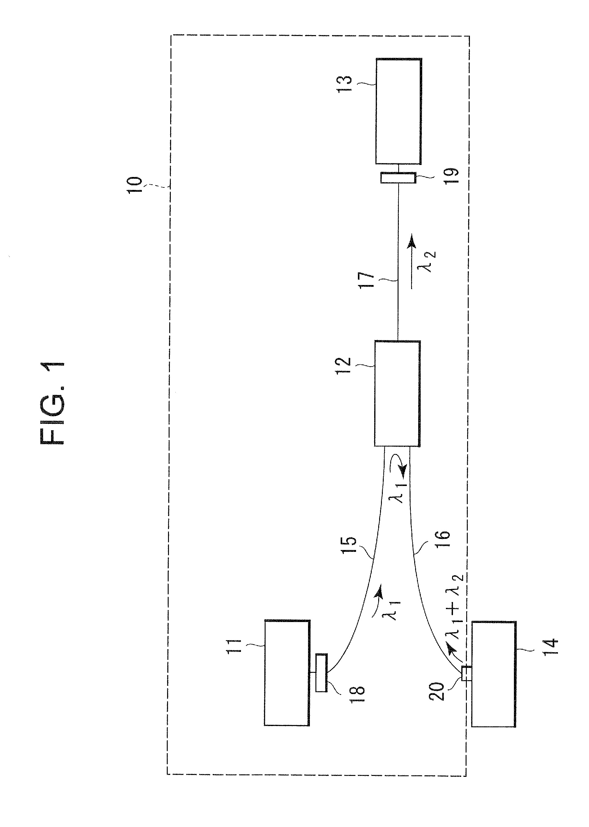
[0060]In the fluorescence detection system 10, capillaries (produced by Nippon Electric Glass Co., Ltd.) were fixed to the ends of the optical fibers 15 to 17. In the structure illustrated in FIG. 4, an LED with a center light emitting wavelength of 470 nm (NSPB500S produced by Nichia Corporation) was used as the LED chip 50. An SELFOC (registered trademark) microlens SLW18 (0.4 pitch) (produced by Nippon Sheet Glass Co., Ltd.) was used as the condenser lens 52. The LED chip 50 was coupled to the optical fiber 15 (SI200 / 250, NA=0.22) through the condenser lens 52 and the excitation filter 18. A short-pass filter with a cutoff wavelength of 490 nm was used as the excitation filter 18.

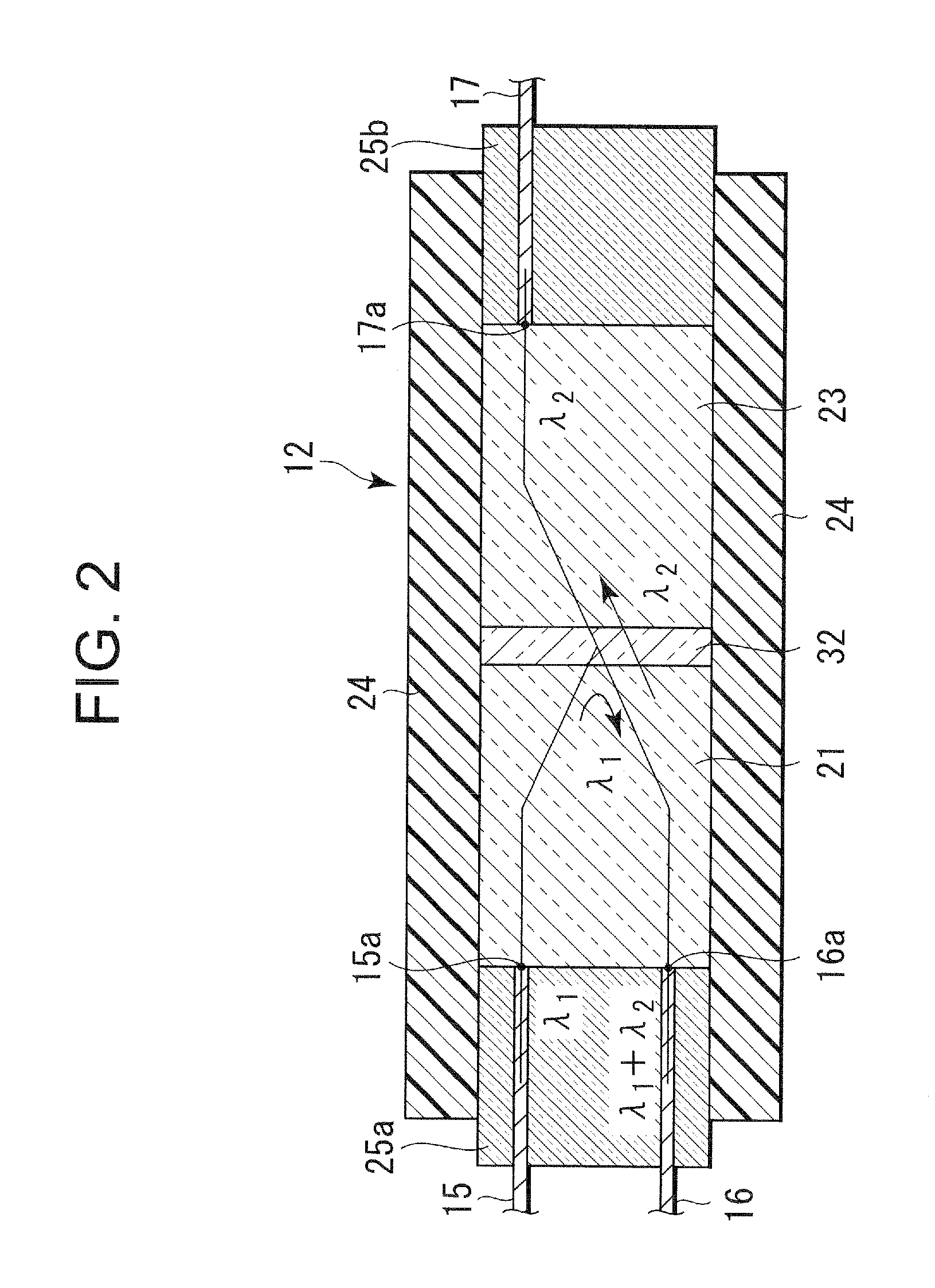
[0061]In the optical multiplexer / demultiplexer 12 illustrated in FIG. 2, an SLW18 (0.23 pitch) (produced by Nippon Sheet Glass Co., Ltd.) was used as the rod lenses 21 and 23 and a long-pass filter which reflects light whose wavelength is 490 nm or less and passes light whose wavelength is 500 nm or more...

example 2

[0064]The fluorescence detection system 10 is different from the example 1 and uses an optical multiplexer / demultiplexer 12′ illustrated in FIG. 6. The optical multiplexer / demultiplexer 12′ used the SLW18 (0.23 pitch) as the rod lenses 21 and 23 and a long-pass filter which reflects light whose wavelength is 490 nm or less and passes light whose wavelength is 500 nm or more as the multiplexing / demultiplexing filter 22. A long-pass filter with a cutoff wavelength of 500 nm used as the detection filter 19 is bonded to the end of a capillary 71b. The detection filter 19 was not arranged on the optical fiber 17. Incidentally, other configurations of the fluorescence detection system 10 in the example 2 are the same as those in the example 1.

[0065]As is the case with the example 1, the light obtained from the sample unit 14 when the aqueous solutions with the concentrations and the water were irradiated with the excitation light was measured five times to obtain signal values from the de...

example 3

[0074]S / B is calculated in the model (with the detection filter 19 and the excitation filter 18) corresponding to the fluorescence detection system 10, which provides S / B of 89700.


PUM

PropertyMeasurementUnit
wavelengthaaaaaaaaaa
cutoff wavelengthaaaaaaaaaa

Abstract

A fluorescence detection system capable of detecting fluorescence with a high sensitivity even if a sample generating fluorescence is small in amount includes a light source emitting excitation light, a probe arranged in opposition to a sample unit, an optical multiplexer/demultiplexer, a detector, a first optical fiber connecting the light source to the optical multiplexer/demultiplexer, a second optical fiber connecting the probe to the optical multiplexer/demultiplexer, and a third optical fiber connecting the detector to the optical multiplexer/demultiplexer. An excitation filter, serving as a short-pass filter, is arranged on the first optical fiber and a detection filter serving as a long-pass filter is arranged on the third optical fiber. The optical multiplexer/demultiplexer includes a multiplexing/demultiplexing filter serving as a long-pass filter.

Description

TECHNICAL FIELD[0001]The present invention relates to a fluorescence detection system, and more particularly, to a fluorescence detection system provided with an optical multiplexer / demultiplexer.BACKGROUND ART[0002]As one example of systems for causing a chemical reaction to occur in a minute space, there has been known a microchemical system. The microchemical system performs mixture, reaction, separation, extraction and detection of a sample in a minute channel formed in a small glass substrate. A sample used in such a microchemical system is generally very small in amount, which requires a high sensitivity detection device for detecting the sample.[0003]When fluorescence is particularly measured using an optical device as a detection device, a fluorescence measurement area is small, so that a higher sensitivity optical device is required. As a method of detecting fluorescence with a high sensitivity, there has been known a laser-induced fluorescence analysis. As an optical devic...

Claims


Application Information

Patent Timeline
Patent Type & Authority Applications(United States)
IPC IPC(8): G01N21/64G01J1/58
CPCG01N2021/6484G01N21/645
Inventor FUKUZAWA, TAKASHI
Owner NIPPON SHEET GLASS CO LTD
Why Eureka
Try Eureka