Method and apparatus of low current startup circuit for switching mode power supplies

a startup circuit and switching mode technology, applied in the field of switching mode power supplies, can solve the problems of increasing system standby power, unregulated power, and consuming more energy, and achieve the effects of reducing standby power, reducing startup current, and reducing the standby power of smps

Active Publication Date: 2010-09-30
BCD SHANGHAI MICRO ELECTRONICS CO LTD
View PDF1 Cites 36 Cited by
  • Summary
  • Abstract
  • Description
  • Claims
  • Application Information

AI Technical Summary

Benefits of technology

[0012]The present invention relates to techniques for reducing standby power in a switching-mode power supply (SMPS). More particularly, embodiments of the present invention provide a startup circuit in an SMPS controller that is configured to require a low startup current. In one embodiment, a reverse-biased diode is used to limit the current consumption of the controller in the startup mode. A low-current feedback circuit is configured to trigger the transition from the startup mode to the normal operation mode when a ...

Problems solved by technology

For example, desktop and laptop computers often receive unregulated power input from various outlets and provide regulated power supplies on the motherboard to the CPU, memories, and periphery circuitry.
Howev...

Method used


Image

  • Method and apparatus of low current startup circuit for switching mode power supplies
  • Method and apparatus of low current startup circuit for switching mode power supplies
  • Method and apparatus of low current startup circuit for switching mode power supplies

Examples


Embodiment Construction

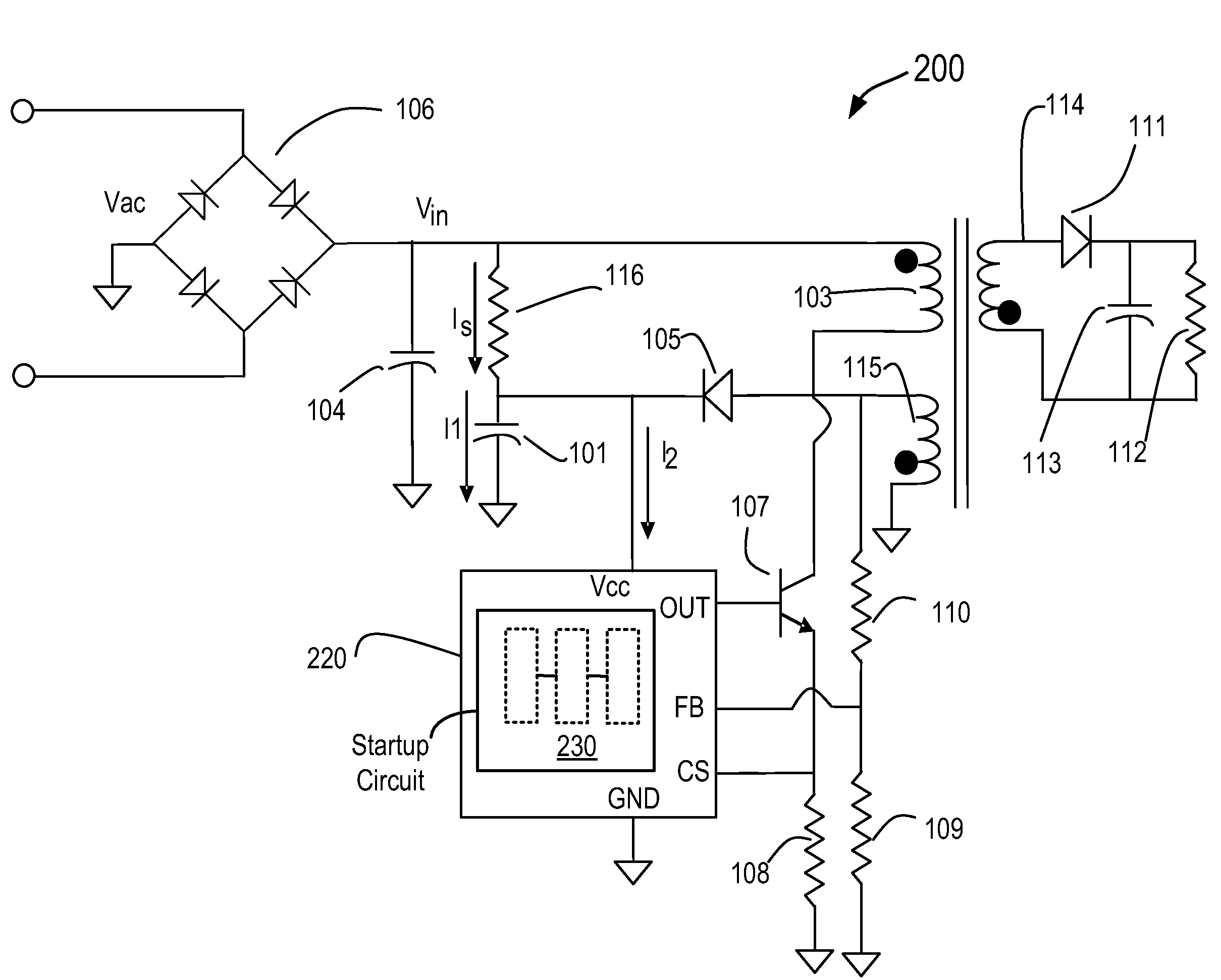
[0027]FIG. 2 is a simplified schematic diagram of a switching-mode power supply (SMPS) system 200 having a switching-mode controller 220 that includes a startup circuit 230 according to an embodiment of the present invention. As shown, power supply 200 is similar to SMPS 100 of FIG. 1, with the exception of controller 220, which is described below. Components in FIG. 2 similar to those in FIG. 1 are labeled with identical reference numerals, and their functions are similar to those of their counterparts described in connection with FIGS. 1A and 1B.

[0028]In FIG. 2, an external DC input supply voltage is provided by AC power source Vac, bridge rectifier 106, and capacitor 104. Resistor 116 and capacitor 101 are used to provide a startup power (by current Is) to controller 220. As described above in connection with SMPS 100 of FIG. 1A, if controller 220 can operate with a low current consumption, resistor 116 can be made large, and the standby power of the SMPS can be reduced. In addit...


PUM


Abstract

A startup circuit for a switching-mode power supply (SMPS) includes a first voltage detector configured to trigger the switching-mode power supply from a startup mode to a normal operation mode when an input supply voltage exceeds a first threshold voltage, a current consumption in the first voltage detector in the startup mode being determined by a reverse leakage current of a diode. A feedback circuit is coupled to the first voltage detector and being capable of maintaining a positive feedback loop with a current consumption of no more than a microampere. A second voltage detector is coupled to the first voltage detector and the feedback circuit, and is configured to trigger the switching-mode power supply to switch from the normal operation mode to the startup mode when the input supply voltage is below a second threshold voltage.

Description

CROSS-REFERENCES TO RELATED APPLICATIONS[0001]This application claims the benefit and priority of Chinese Application No. 200910131728.7, filed Mar. 27, 2009, commonly assigned and hereby incorporated by reference in its entirety for all purposes.BACKGROUND OF THE INVENTION[0002]The present invention relates to switching-mode power supplies (SMPS), and more particularly to a startup circuit that is configured to produce a low startup current for switching-mode power supplies.[0003]Regulated power supplies are indispensable in modern electronics. For example, desktop and laptop computers often receive unregulated power input from various outlets and provide regulated power supplies on the motherboard to the CPU, memories, and periphery circuitry. Regulated power supplies may be used in a wide variety of consumer applications, such as home appliances, automobiles, and portable chargers for mobile electronic devices, etc.[0004]A switching-mode power supply (SMPS) is an electronic power...

Claims


Application Information

Patent Timeline
IPC IPC(8): G05F5/00
CPCH02M1/36
Inventor ZONG, QIANGFANG, SHAOHUAFEI, REIXIAXIE, JIA
Owner BCD SHANGHAI MICRO ELECTRONICS CO LTD
Why Eureka
Try Eureka