Using s-parameter measurements to manage SAR and transmit gain

a technology of sar and sparameter, applied in the field of magnetic resonance imaging systems, can solve the problems of not taking into account the differences in electrical properties, and the current techniques for controlling the electromagnetic signals of a particular sar may be relatively inexa

Active Publication Date: 2010-09-30
GENERAL ELECTRIC CO
View PDF11 Cites 45 Cited by
  • Summary
  • Abstract
  • Description
  • Claims
  • Application Information

AI Technical Summary

Problems solved by technology

However, current techniques for controlling the electromagnetic signals to a particular SAR may be relatively inexact, and may not account for differences in electrical properties among various objects that may be scanned by the scanner.

Method used


Image

  • Using s-parameter measurements to manage SAR and transmit gain
  • Using s-parameter measurements to manage SAR and transmit gain
  • Using s-parameter measurements to manage SAR and transmit gain

Examples


Embodiment Construction

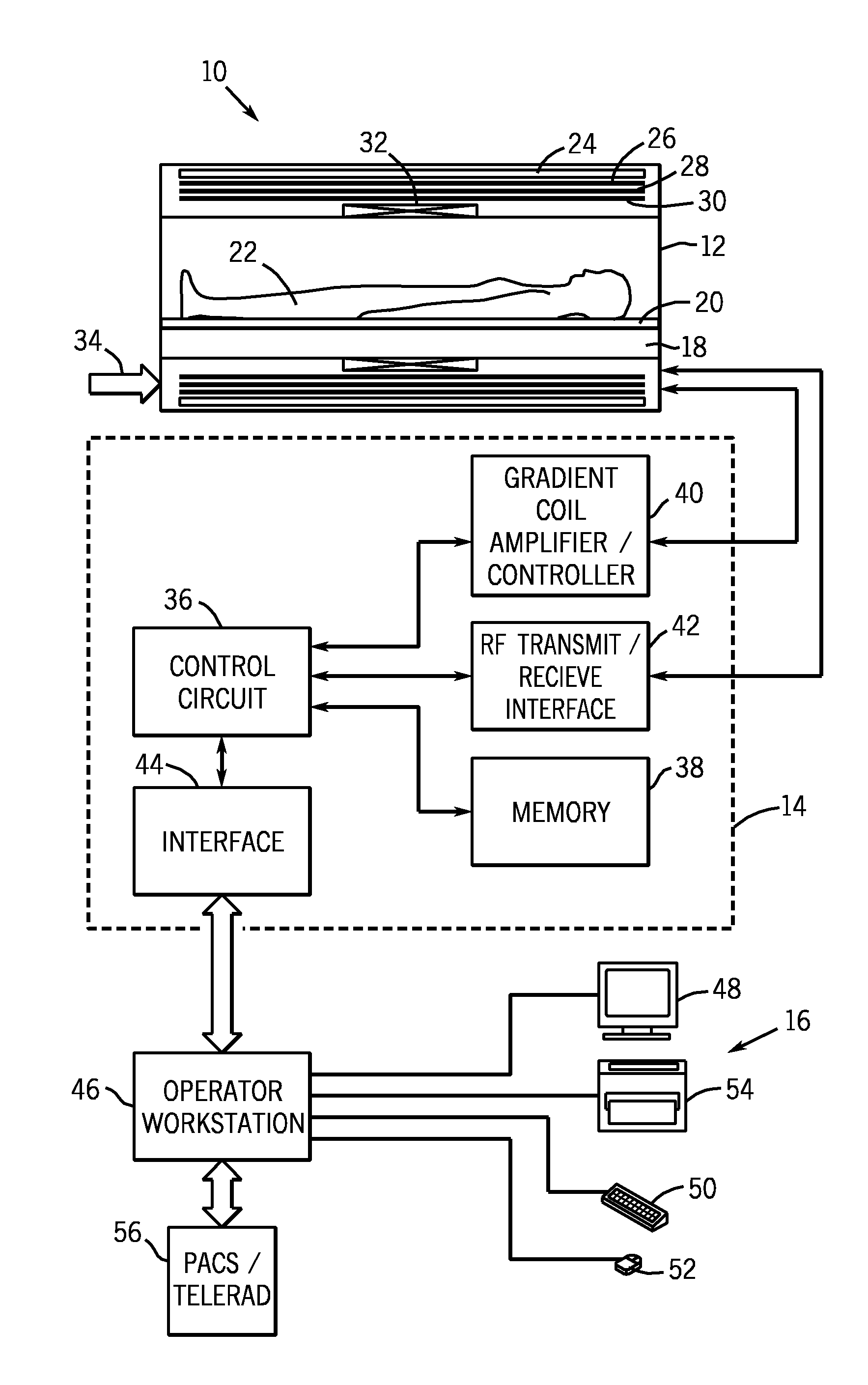
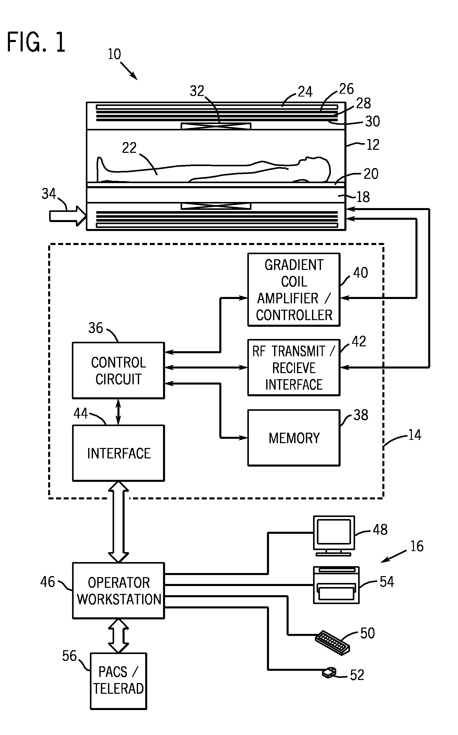
[0014]Turning now to the drawings, and referring first to FIG. 1, a magnetic resonance imaging (MRI) system 10 is illustrated diagrammatically as including a scanner 12, scanner control circuitry 14, and system control circuitry 16. While the MRI system 10 may include any suitable MRI scanner or detector, in the illustrated embodiment the system includes a full body scanner comprising an imaging volume 18 into which a table 20 may be positioned to place a patient 22 in a desired position for scanning. The scanner 12 may additionally or alternatively be configured to target certain anatomy, such as the head or neck.

[0015]The scanner 12 may include a series of associated coils for producing controlled magnetic fields, for generating radio frequency (RF) excitation pulses, and for detecting emissions from gyromagnetic material within the patient in response to such pulses. In the diagrammatical view of FIG. 1, a main magnet 24 is provided for generating a primary magnetic field general...


PUM


Abstract

Systems and methods for controlling a magnetic resonance imaging system are provided. In one embodiment, a magnetic resonance imaging system includes a radio frequency coil with a plurality of conductive coil elements, control circuitry that determines, based at least in part on a measurement of scattering parameters, a plurality of forward voltages that will cause power deposition into an object within a predetermined specific absorption rate, and an amplifier configured to apply the determined plurality of forward voltages respectively to the plurality of coil elements. The control circuitry may determine the plurality of forward voltages based at least in part on an unloaded measurement of scattering parameters and a loaded measurement of scattering parameters.

Description

BACKGROUND[0001]The subject matter disclosed herein relates generally to magnetic resonance imaging systems and, more particularly, to managing specific absorption rates into patients scanned by magnetic resonance imaging systems.[0002]Magnetic resonance imaging (MRI) systems enable imaging based on a primary magnetic field, a radio frequency (RF) pulse, and time-varying magnetic gradient fields that interact with specific nuclear components in an object, such as hydrogen nuclei in water molecules. The magnetic moments of such nuclear components may attempt to align with the primary magnetic field, but subsequently precess at a characteristic frequency known as the Larmor frequency. An RF pulse at or near the Larmor frequency of such nuclear components may cause the magnetic moments to be rotated. When the RF pulse has ended, the magnetic moments may attempt to realign with the primary magnetic field, emitting a detectable signal.[0003]Such electromagnetic signals may penetrate the ...

Claims


Application Information

Patent Timeline
Patent Type & Authority Applications(United States)
IPC IPC(8): G01R33/32
CPCG01R33/288G01R33/5659G01R33/5612G01R33/3415
Inventor MCKINNON, GRAEME COLIN
Owner GENERAL ELECTRIC CO
Why Eureka
Try Eureka