Object detection

a waveform and object technology, applied in the field of waveform generation, can solve the problems of non-repetitive interference, achieve the effects of reducing the frequency of the interference, reducing the interference, and reducing the interference ra

Inactive Publication Date: 2010-09-30
MITSUBISHI ELECTRIC CORP
View PDF32 Cites 27 Cited by
  • Summary
  • Abstract
  • Description
  • Claims
  • Application Information

AI Technical Summary

Benefits of technology

[0020]Such an arrangement will ensure an enhanced resistance to mutual in-band interference caused by other users operating in the same region and sharing the same frequency band ΔF. This is because, as will be clear from the description set out below, there is a low probability that users will be emitting similar frequencies at the same time. Because of the limited bandwidth of the processing circuitry, e.g. the low pass filter/amplifier LPA of FIG. 1, significantly different frequencies will be rejected. Even if two transmitters generate crossing frequency/time slopes, the mutual interference will be very brief and non-repetitive, and therefore cause little if any problem. In the unlikely event that two transmitte

Problems solved by technology

Furthermore, even this remote possibility would cause non-repetitive in

Method used


Image

  • Object detection
  • Object detection
  • Object detection

Examples


case b suppose

[0110 now that equal probability, 1 / 5, of each of the five tones is required. In this case, the threshold values should be chosen as: T21=12, T31=22 and T32=39. Although the tone probabilities are equal, the slope probabilities are now all different: P(SL=1)=0.42, P(SL=2)=0.33 and P(SL=3)=0.25.

case c

[0111 In some applications, it may be required to reduce the probability of occurrence of one of the slopes. For example, selecting the thresholds as: T21=59, T31=20 and T32=21, will result in the following slope probabilities: P(SL=1)=P(SL=3)=0.49, and P(SL=2)=0.02. In this case, the tone probabilities will be as follows: P(F1)=P(F5)=0.19, P(F2)=P(F4)=0.25 and P(F3)=0.12.

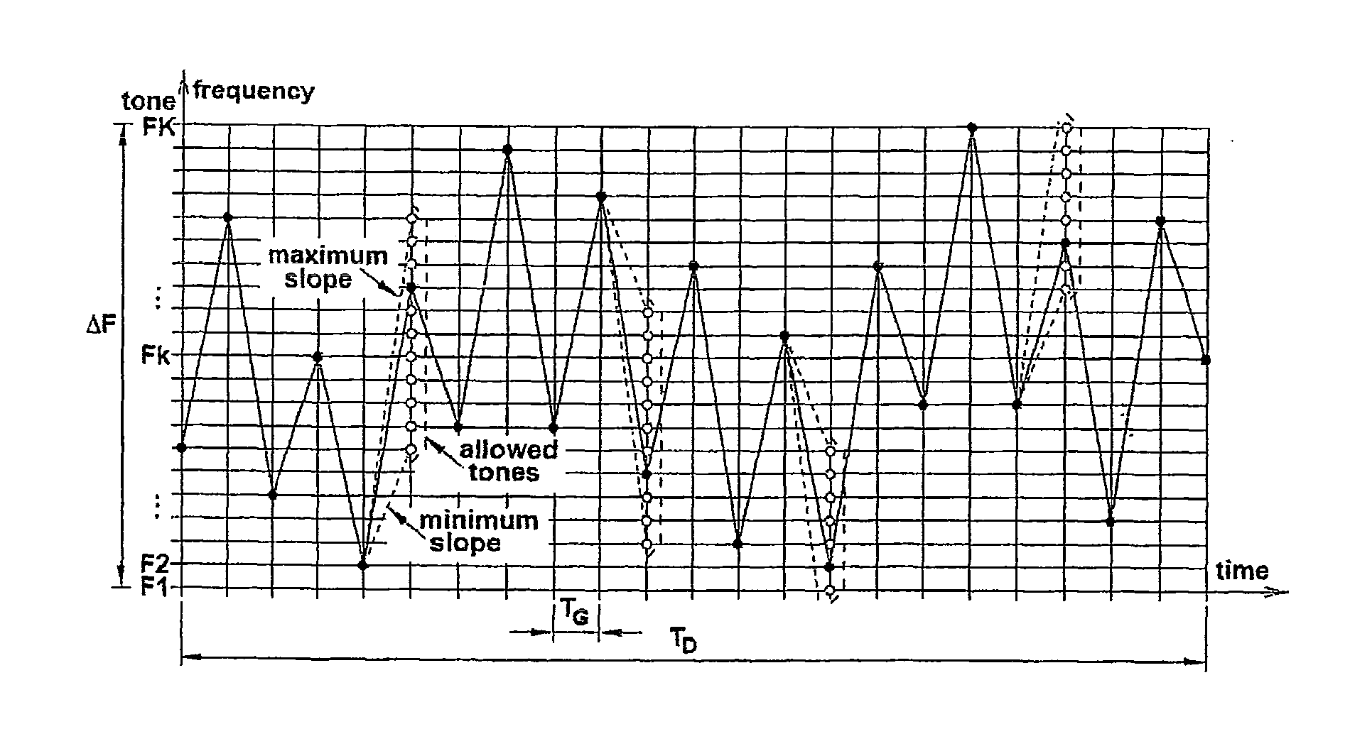
[0112]FIG. 10 shows schematically the empirical histograms of tones and slopes obtained for each of the above cases, and FIG. 11 depicts examples of trajectories of corresponding frequency walks. For illustrative purposes, the frequency of the tones and time intervals are expressed in practically useful units. As seen, different values of tone and slope probabilities result in different appearance of the trajectories.

[0113]FIG. 12 is an example of the application of a digital glissando controller GTR constructed in accordance with the invention to automotive FMCW radar. In the example shown, the waveform generator ...


PUM


Abstract

An object ranging system operates by transmitting alternating up and down frequency sweeps which have randomly distributed slopes as a result of random selection of local frequency peaks and valleys according to predetermined probability tables, and determining the beat frequency obtained when combining the transmitted signal with its reflection from an object.

Description

FIELD OF THE INVENTION[0001]This invention relates to a method and apparatus for the generation of waveforms suitable for use in object detection and ranging, for example by modulating the carrier frequency of a microwave radar. The invention is particularly suited for systems operating in environments with high levels of noise and interference, and is especially, but not exclusively, applicable to automotive FMCW radar intended to operate in multi-user scenarios.BACKGROUND OF THE INVENTION[0002]The growing demand for autonomous cruise control and collision warning / avoidance systems has stimulated the development of frequency-modulated continuous-wave (FMCW) automotive radar. Most of these radars under development operate in the 77-GHz band, which has been reserved for these applications.[0003]A functional block diagram of FMCW radar is depicted in FIG. 1. The system comprises a triangular waveform generator WFG, a voltage-controlled oscillator VCO acting also as an up-converter, a ...

Claims


Application Information

Patent Timeline
IPC IPC(8): G01S13/34G01S13/02
CPCG01S13/345G01S7/023G01S7/0232
Inventor SZAJNOWSKI, WIESLAW JERZY
Owner MITSUBISHI ELECTRIC CORP
Why Eureka
Try Eureka