Method for anchoring a fastening element in a mineral component, and fastening element for mineral components

a technology of fastening elements and mineral components, which is applied in the direction of threaded fasteners, fastening means, screws, etc., can solve the problems of conflicting requirements for settability and load-bearing capacity, difficult or impossible setting of fastening elements, and unsuitable use of thread cutters for metal in mineral components. , to achieve the effect of improving the removal characteristics, and reducing the wear on the cutting edg

Inactive Publication Date: 2010-09-30
HILTI AG
View PDF4 Cites 38 Cited by
  • Summary
  • Abstract
  • Description
  • Claims
  • Application Information

AI Technical Summary

Benefits of technology

[0038]The at least one cutting edge is also advantageously provided with a bevel, thus reducing the wear on the cutting edge during the setting process. The bevel angle is preferably 1° to 30°, advantageously 5° to 15°. The width of the bevel is preferably 0.05 mm to 1 mm, advantageously 0.2 mm to 0.5 mm. The undercut of the bevel, which in the present context is understood to mean the section of the bevel extending essentially parallel to the radial cross section of the shank, is 0.1 mm to 5 mm, particularly advantageously 0.5 mm to 3 mm. In the present context, “bevel” also refers to a rounded cutting edge having a radius of preferably 0.02 mm to 1 mm, advantageously 0.05 mm to 0.5 mm. When multiple cutting edges are pr...

Problems solved by technology

In mineral components or substrates, the transmittable shear forces are much smaller than the transmittable compressive forces, for which reason thread cutters for metal are unsuitable for use in mineral components.
The design of generic fastening elements results in conflicting requirements for settability and load-bearing capacity.
Since the fastening element is not able to adapt to the inscribed bore cylinder, i.e., to the bore hole having negative axial deviations, the fastening element is difficult or impossible to set.
A disadvantage of the known approach is that, despite the improved setting characteristics compare...

Method used


Image

  • Method for anchoring a fastening element in a mineral component, and fastening element for mineral components
  • Method for anchoring a fastening element in a mineral component, and fastening element for mineral components
  • Method for anchoring a fastening element in a mineral component, and fastening element for mineral components

Examples


Embodiment Construction

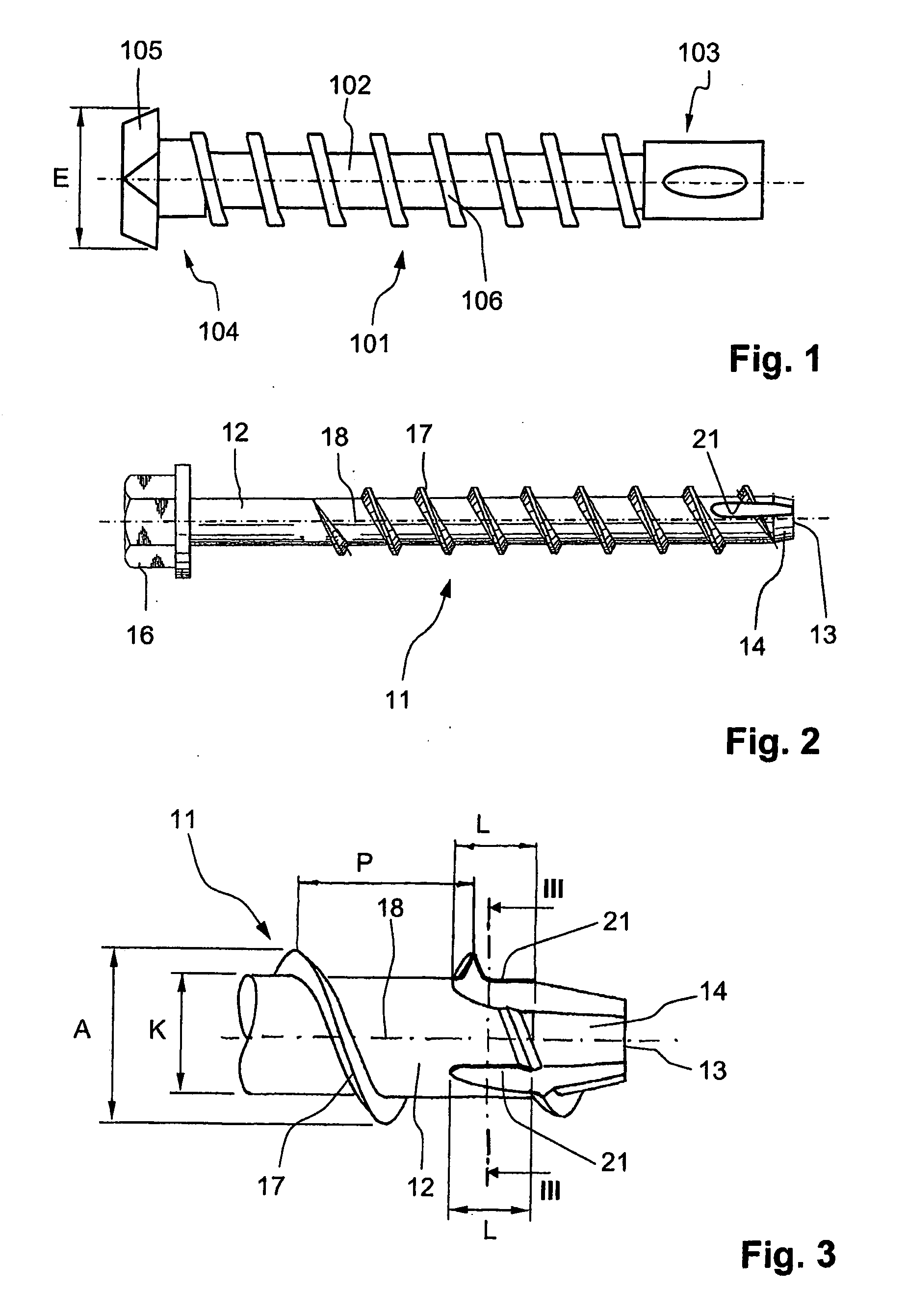
[0055]FIG. 1 shows a drill bit 101 which has a drill bit shank 102 and a nominal drill bit diameter. At one end, drill bit shank 102 is provided with an insertion end 103 for placing drill bit 101 in a drill, not illustrated. A drill bit head 104 having a plate-shaped cutting element 105 is provided at the other end of drill bit shank 102. The transverse extension of cutting element 105 defines drill bit cross-corner width E of drill bit 101. A conveying spiral 106 extends along drill bit shank 102, between drill bit head 104 and insertion end 103, for conveying the drill dust and / or drill cuttings produced during drilling from bore hole 2.

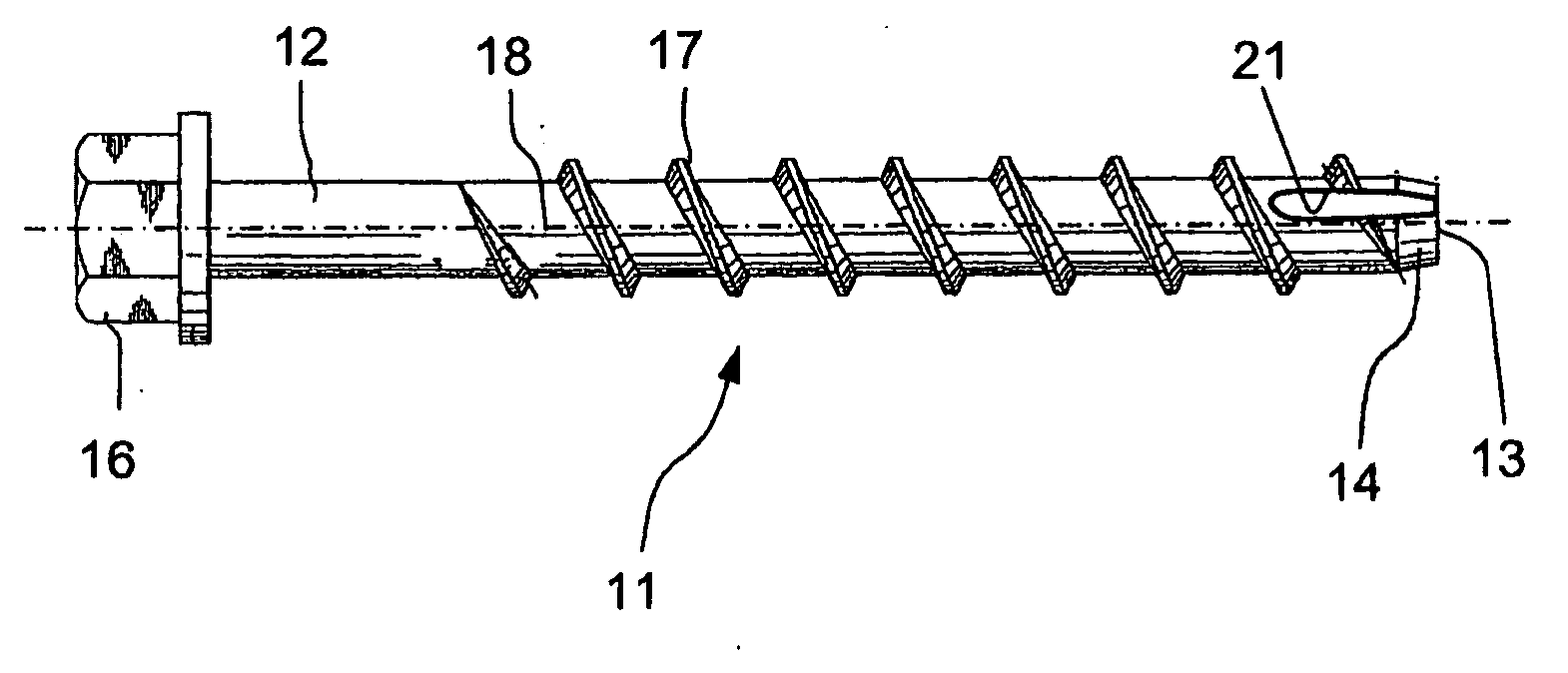
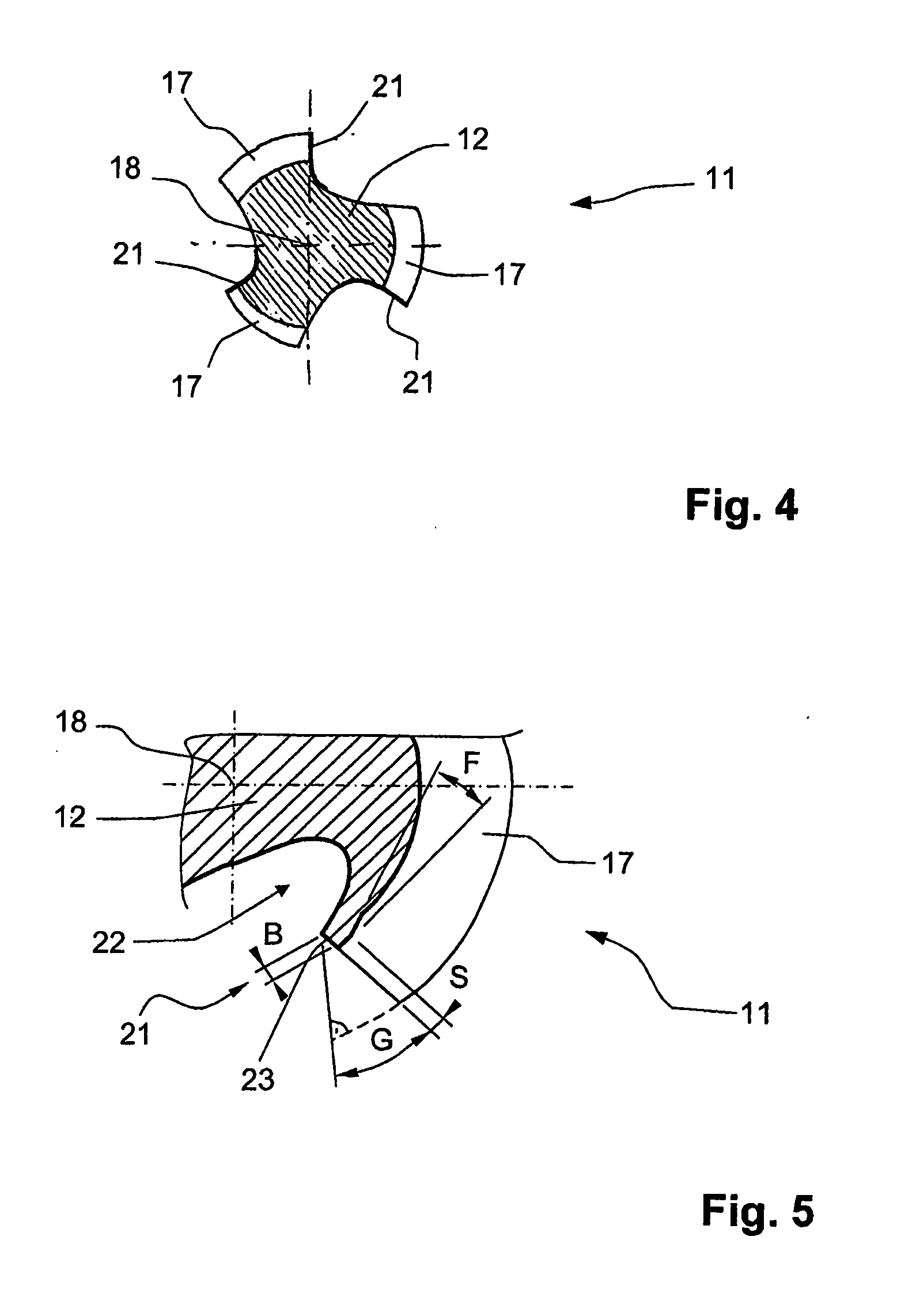
[0056]Fastening element 11 for mineral components made of concrete or masonry, for example, illustrated in FIGS. 2 through 5, is a self-tapping screw having a cylindrical shank 12. On a first free end 13, shank 12 has an insertion section 14 which tapers toward free end 13 of shank 12, and on a second end 15 has a hexagonal head as rotary engageme...


PUM


Abstract

A method is described for anchoring a fastening element (11) in a mineral component (1), in which a bore hole (2) is provided in the component (1) using a drill bit having a nominal drill bit diameter, and a fastening element (11) is then screwed into the provided bore hole (2). The fastening element (11) has a shank (12) which is provided with rotary engagement device (16) for a setting tool, and has a core diameter (K) and cutting edges (21) on a first end region. The fastening element has a self-tapping thread (17) in which the difference between the outer diameter of the thread (17) and the core diameter (K) of the shank (12) corresponds to 0.05 to 0.7 times the pitch of the thread (17). A drill bit is used which has a nominal drill bit diameter corresponding to 0.95 to 1.10 times the core diameter (K) of the shank (12). Also described is a fastening element (11) for anchoring in a mineral component (1).

Description

[0001]This claims the benefit of German Patent Application No. DE 10 2009 001815, filed Mar. 24, 2009 and hereby incorporated by reference herein.[0002]The present invention relates to a method for anchoring a fastening element in a mineral component. The present invention further relates to a fastening element for mineral components.BACKGROUND[0003]For anchoring a fastening element in a mineral component or substrate composed of concrete or masonry, for example, first a bore hole is provided in the component with the aid of a drill bit which has a nominal drill bit diameter, and a fastening element is then screwed into the bore hole produced. The fastening element has a shank which is provided with rotary engagement means or device for a setting tool and has a core diameter, as well as a self-tapping thread whose outer diameter is greater than the inner diameter of the bore hole.[0004]When the fastening element is screwed into the bore hole, the turns of the thread cut or press int...

Claims


Application Information

Patent Timeline
IPC IPC(8): F16B25/02
CPCF16B25/00F16B25/0026F16B25/0084F16B25/0073F16B25/0047
Inventor BIANCHI, PIETROSANDER, BERNHARDROSENKRANZ, FALKGSTACH, PETEROBERNDORFER, GEORGWINKLER, BERNHARD
Owner HILTI AG
Why Eureka
Try Eureka