Subastrate for a magnetic disk and method of manufacturing the same

a technology of magnetic disk and substrate, which is applied in the direction of manufacturing tools, lapping machines, instruments, etc., can solve the problems of reducing workability and damaging the substrate, and achieve the effect of reducing workability and smoothing the main surface of the substra

Inactive Publication Date: 2010-09-30
HOYA CORP
View PDF7 Cites 16 Cited by
  • Summary
  • Abstract
  • Description
  • Claims
  • Application Information

AI Technical Summary

Benefits of technology

[0006]On the other hand, however, as the smoothness of the substrate main surfaces increases by a combination of the secondary polishing materials (polishing pads, polishing abrasive particles, etc.), there arises a problem that, as shown at (a) in FIG. 4, the substrates 4, after the double-side polishing, adhere randomly to a polishing pad 9a on the upper polishing surface plate side and a polishing pad 9b on the lower polishing surface plate side. This reduces the workability and damages the substrates 4 in a substrate unloading (substrate removal) operation after the double-side polishing.
[0007]In order to solve such a problem, it is considered, as shown in FIG. 5, to provide grooves 9c on the polishing pad 9a to form a gap between the substrates 4 and the polishing pad 9a, thereby making it easy to strip the substrates 4 from the polishing pad 9a with the use of the fact that air enters this gap. However, by providing the grooves 9c on the polishing pad 9a in this manner, a level difference is formed on the polishing pad 9a and it may happen that the waviness (microwaviness) of the substrates 4 is degraded after the polishing and that the polishing pad 9a is stripped from the polishing surface plate due to the substrates 4.
[0008]This invention has been made in view of the above and has an exemplary object to provide a magnetic disk substrate capable of preventing it from adhering randomly to an upper or lower polishing surface plate after polishing without degrading the substrate quality and further to provide a method of manufacturing such a magnetic disk substrate.

Problems solved by technology

This reduces the workability and damages the substrates 4 in a substrate unloading (substrate removal) operation after the double-side polishing.

Method used


Image

  • Subastrate for a magnetic disk and method of manufacturing the same
  • Subastrate for a magnetic disk and method of manufacturing the same
  • Subastrate for a magnetic disk and method of manufacturing the same

Examples


example 1

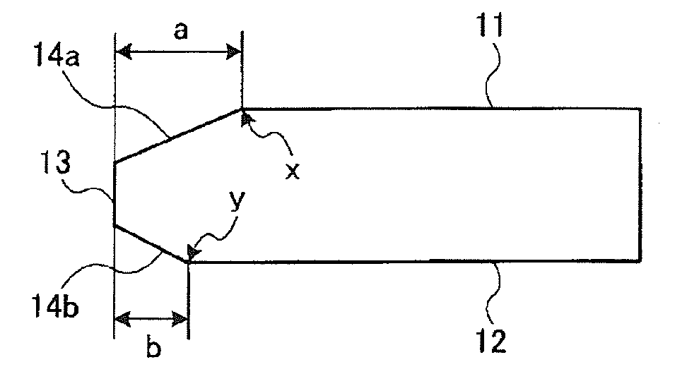
[0046]First, a molten aluminosilicate glass was formed into a disk shape by direct pressing using upper, lower, and drum molds, thereby obtaining an amorphous plate-like glass blank. In this event, the diameter of the blank was 66 mm. Then, first lapping was applied to both main surfaces of the blank, then, using a cylindrical core drill, processing (coring) was carried out to form a hole at a central portion of the blank, thereby obtaining an annular glass substrate having an outer peripheral edge face and an inner peripheral edge face. Then, chamfering (chamfered face forming process) was carried out to form chamfered faces at end portions (outer peripheral end portion and inner peripheral end portion), thereby obtaining a glass substrate with a diameter of 2.5 inches. In this event, the chamfering was carried out so that the chamfered length of the upper main surface was made longer than that of the lower main surface. Specifically, the ratio a / b between the distance a from a bou...

example 2

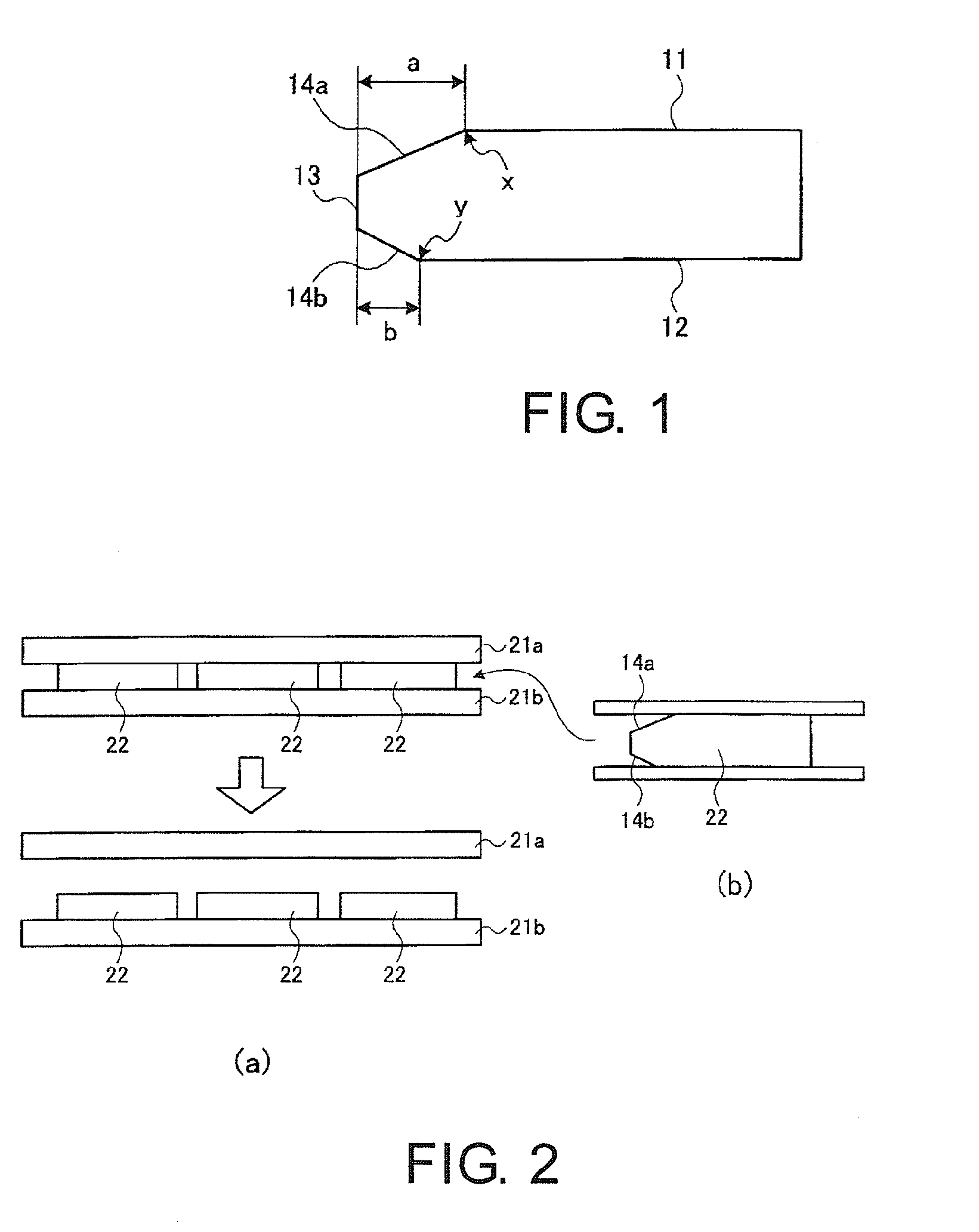
[0049]First and second polishing processes were applied to glass substrates in the same manner as in Example 1 except that the ratio a / b was set to 2. Polishing was carried out by placing 100 glass substrates in the polishing machine in the state where main surfaces with a longer chamfered length were facing the upper polishing surface plate side. The polishing surface plates were detached after the completion of the polishing and, as a result, the number of the glass substrates adhering to the upper polishing surface plate was zero. The microwaviness of the glass substrates after the polishing was measured in the same manner as in Example 1 and, as a result, it was 1.1 Å and thus was excellent.

example 3

[0050]First and second polishing processes were applied to glass substrates in the same manner as in Example 1, wherein the ratio a / b was set to 1.6 as in Example 1. Polishing was carried out by placing 100 glass substrates in the polishing machine in the state where main surfaces with a longer chamfered length were facing the lower polishing surface plate side. The polishing surface plates were detached after the completion of the polishing and, as a result, the number of the glass substrates adhering to the lower polishing surface plate was zero. The microwaviness of the glass substrates after the polishing was measured in the same manner as in Example 1 and, as a result, it was 1.2 Å and thus was excellent.


PUM

PropertyMeasurementUnit
distanceaaaaaaaaaa
diameteraaaaaaaaaa
diameteraaaaaaaaaa

Abstract

In a magnetic disk substrate having first and second chamfered faces respectively connecting between first and second main surfaces opposite to each other and an edge face located between the first and second main surfaces, the ranges of the first and second chamfered faces are specified. Specifically, the distance a from a first boundary portion being a boundary between the first main surface and the first chamfered face to a point of intersection between the first main surface and an extended line of the edge face and the distance b from a second boundary portion being a boundary between the second main surface and the second chamfered face to a point of intersection between the second main surface and an extended line of the edge face are set to satisfy a / b≧1.6.

Description

CROSS REFERENCE TO RELATED APPLICATIONS[0001]This application is claims the benefit of priority from Japanese Patent Application No. 2009-081699, filed on Mar. 30, 2009, and Japanese Patent Application No. 2009-293759, filed on Dec. 25, 2009, the disclosures of which are incorporated herein in their entirety by reference.TECHNICAL FIELD[0002]This invention relates to a substrate for a magnetic disk for use in a magnetic disk device such as a hard disk drive (HDD) and to a method of manufacturing the same. Hereinafter, a substrate for a magnetic disk will also be referred to as a magnetic disk substrate.BACKGROUND[0003]Currently, a magnetic disk having a magnetic layer on both main surfaces of a disk-shaped substrate is widely used in a hard disk drive. With the increase in capacity of the hard disk drive, a recording medium has shifted to the perpendicular magnetic recording type. Following this, low roughness, low waviness, low defect, flatness in end portion shape, and so on are c...

Claims


Application Information

Patent Timeline
Patent Type & Authority Applications(United States)
IPC IPC(8): G11B5/73G11B5/84B24B1/00B24B37/08G11B5/82
CPCG11B5/8404G11B5/7315G11B5/73921
Inventor TSUCHIYA, HIROSHIFUKADA, JUNPEIMIZUNO, TAKANORI
Owner HOYA CORP
Why Eureka
Try Eureka