Motion assist apparatus

a technology of motion assist and apparatus, which is applied in the direction of gymnastic exercise, instruments, manufacturing tools, etc., can solve the problems of user injury in muscles and joints, inability to assist mutually different movements, and finger joint injury, so as to prevent finger joint damage, facilitate damage, and effective rehabilitation machine

Inactive Publication Date: 2010-09-30
PANASONIC HEALTHCARE HLDG CO LTD
View PDF8 Cites 63 Cited by
  • Summary
  • Abstract
  • Description
  • Claims
  • Application Information

AI Technical Summary

Benefits of technology

[0049]In accordance with the present invention, by allowing the wire unit of the palm-side actuator, attached to each of finger portions of the attaching member, to arrange wires with repetitive wide and narrow portions, so that the wires of the wire unit are placed with a triangular shape for each of spaces between the joints. Therefore, with respect to the wire unit linearly pulled by extension and contraction of the rubber artificial muscle, two portions adjacent to each other on the joint of the finger of the user, can be pulled along an extending direction of the finger, that is, in an extending direction of the wire unit, without causing a deviation from the side in the width direction of the finger portion to the center, or from the center to the side in the width direction thereof. Therefore, without causing an excessive force in an impossible direction to the joint of the finger that is easily damaged even upon application a small external force, the force can be exerted on the finger joint

Problems solved by technology

For this reason, in the case where the motion assist is carried out in a direction different from a desired direction of the user, or in the case where the motion assist is given with a force different from that desired by the user, for example, with an excessively strong force, the user might be hurt in his or her muscles and joints.
For this reaso

Method used


Image

  • Motion assist apparatus
  • Motion assist apparatus
  • Motion assist apparatus

Examples


Embodiment Construction

[0068]Referring to drawings, the following description will discuss a motion assist apparatus in accordance with one embodiment of the present invention.

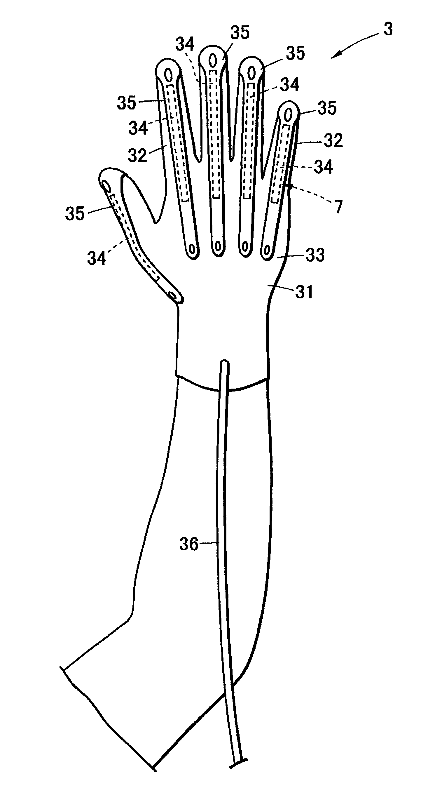
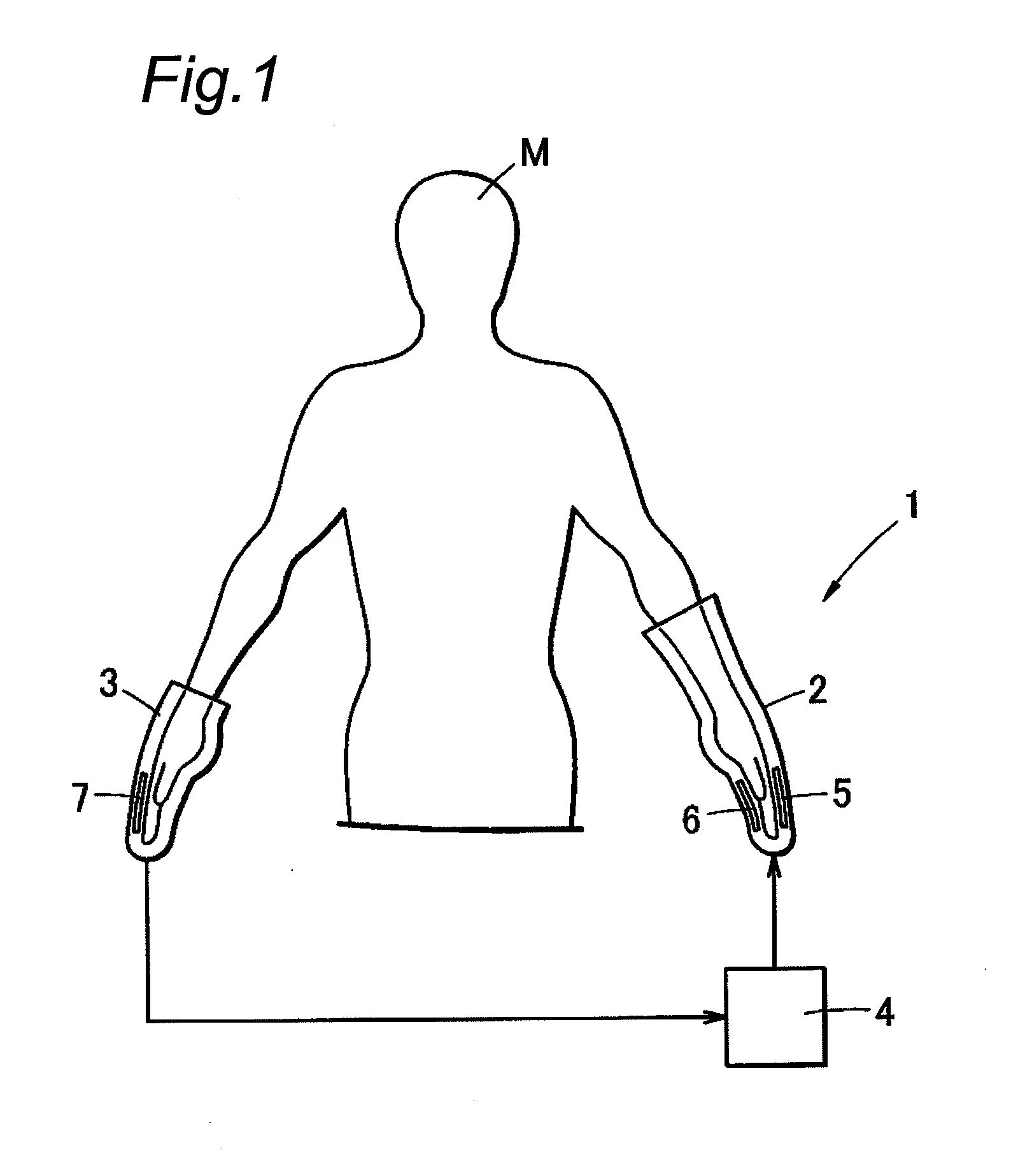
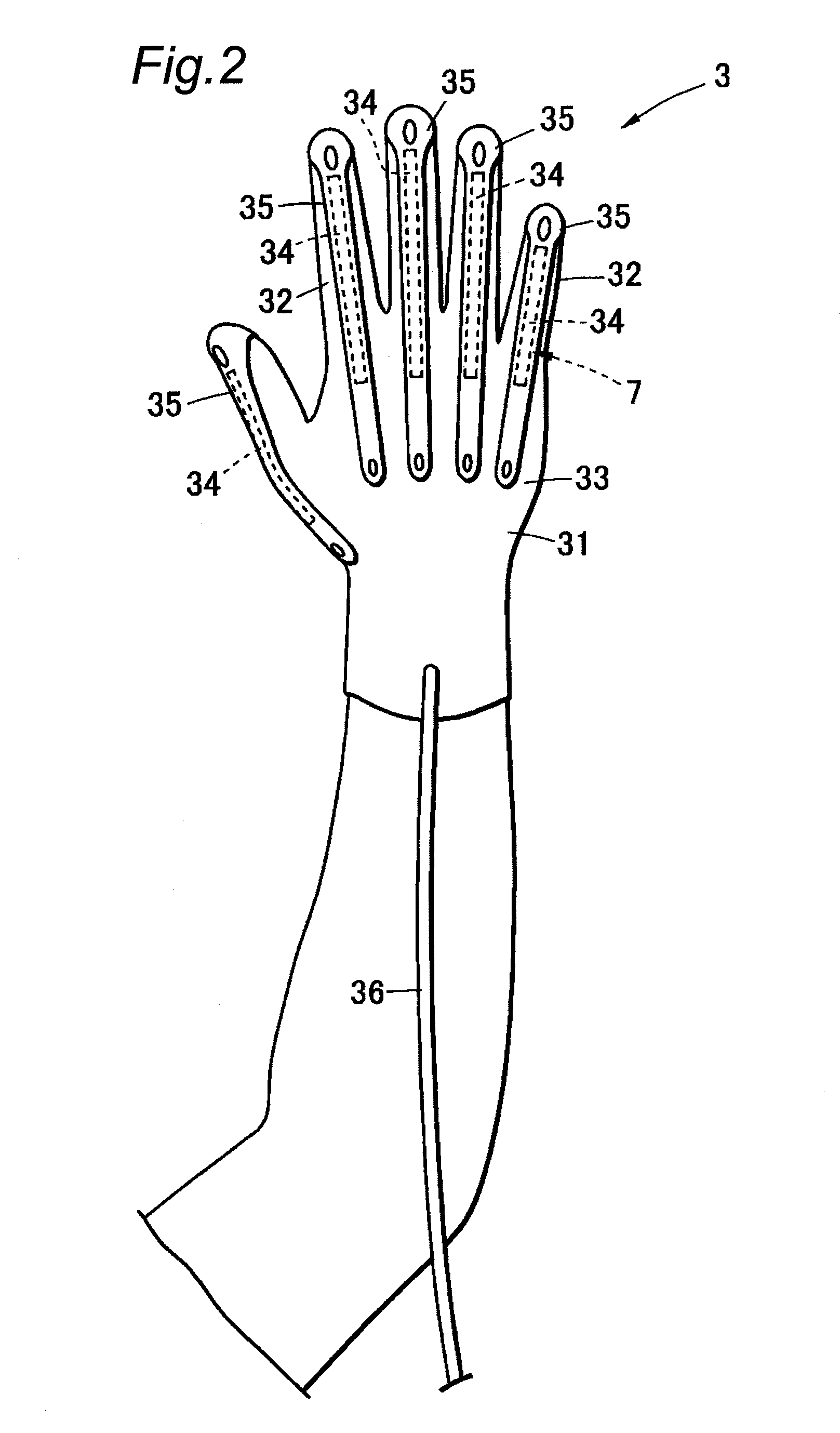
[0069]FIG. 1 is a view that shows a structure of a power assist glove in accordance with an embodiment of the motion assist apparatus of the present invention. As shown in FIG. 1, a power assist glove 1 is provided with a sensor unit 3, an actuator unit 2, and a control unit 4. The sensor unit 3 and the actuator unit 2 are respectively attached to two hands of a user M. In the present embodiment, the actuator unit 2 is attached to a left hand of the user, and the sensor unit 3 is attached to a right hand of the user; however, these may be respectively attached to the opposite hands reversely.

[0070]With this structure, the power assist glove 1 allows the control unit 4 to detect movements of fingers to which the glove is attached by a sensor 7 attached to the sensor unit 3 so that the other corresponding fingers are moved by actuator...


PUM


Abstract

A motion assist apparatus is provided with an attaching member that has a glove shape with finger portions and a middle hand portion that is attachable to one of hands of a user, a back-side actuator that is freely expanded and contracted, and bridged between a tip of each of the finger portions and the middle hand portion on the back side of the attaching member, and a palm-side actuator that is freely expanded and contracted, and bridged between the tip of each of the finger portions and the middle hand portion on the palm side of the attaching member, and in this structure, the palm-side actuator is provided with a wire unit formed of two wires that are disposed on each of the finger portions on the palm side from the tip of each of the finger portions on the back side to the middle hand portion along the finger portion, passing through two side portions of the finger portion, so that intervals therebetween are made different at respective positions corresponding to joints of the finger portion, and rubber artificial muscle is coupled to the wire unit and is formed on the middle hand portion.

Description

TECHNICAL FIELD[0001]The present invention relates to a motion assist apparatus that assists motions of fingers and the like of a human body by using an actuator provided with rubber artificial muscles.BACKGROUND ART[0002]Conventionally, various training apparatuses that are used for patients having a handicap on any of motor functions so as to recover a muscle force of any of portions, such as a hand, a leg, a trunk, or a neck, have been developed. Moreover, in order to assist daily motions of elder people having weakened physical strength or to reduce physical loads of a caregiver, various apparatuses, such as a walking assist apparatus, a lift device for use in going-up and down stairs, or a holding-use lift device, have been developed for a purpose of assisting muscle forces.[0003]In these devices, a technique in which, by allowing a user to put an apparatus on, the user can use the apparatus to assist his or her muscle force, has been proposed, for example, in JP-A No. 2001-286...

Claims


Application Information

Patent Timeline
IPC IPC(8): A61H1/02
CPCA61H1/0285A61H2201/1238G06F3/014A61H2201/5058B25J9/0006A61H2201/165
Inventor FUJIMOTO, HIROMICHISHIROGAUCHI, GOUEDA, KEISUKEHORI, MOTOSHIMIZUTANI, TATSURO
Owner PANASONIC HEALTHCARE HLDG CO LTD
Why Eureka
Try Eureka