Systems for announcing the health of aircraft control elements

a technology for controlling elements and aircraft, applied in the direction of automatic actuation, air-flow influencers, instruments, etc., can solve the problems of insufficient analysis of the operating characteristics of drive train components in actual use, limited utility of known vibration test systems, and large operating cycles of type drives. , to achieve the effect of reducing the effectiveness of ball bearings and increasing friction

a technology for controlling elements and aircraft, applied in the direction of automatic actuation, air-flow influencers, instruments, etc., can solve the problems of insufficient analysis of the operating characteristics of drive train components in actual use, limited utility of known vibration test systems, and large operating cycles of type drives. , to achieve the effect of reducing the effectiveness of ball bearings and increasing friction

US20100250047A1Active Publication Date: 2010-09-30PENDICOM LLC

Image

  • Systems for announcing the health of aircraft control elements
  • Systems for announcing the health of aircraft control elements
  • Systems for announcing the health of aircraft control elements

Examples


Embodiment Construction

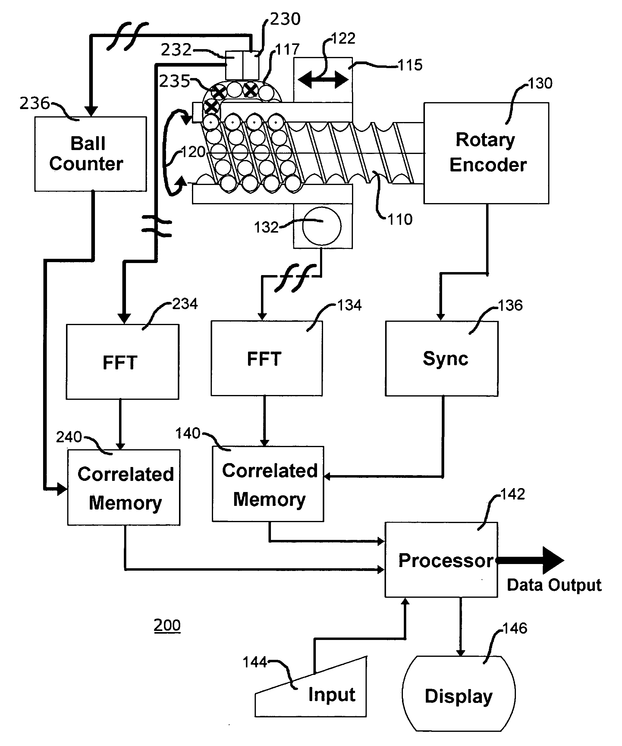
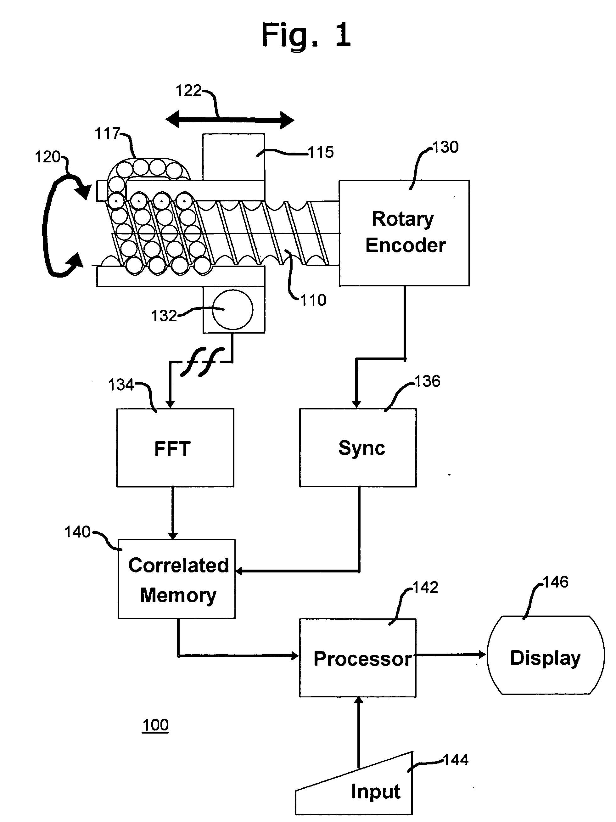
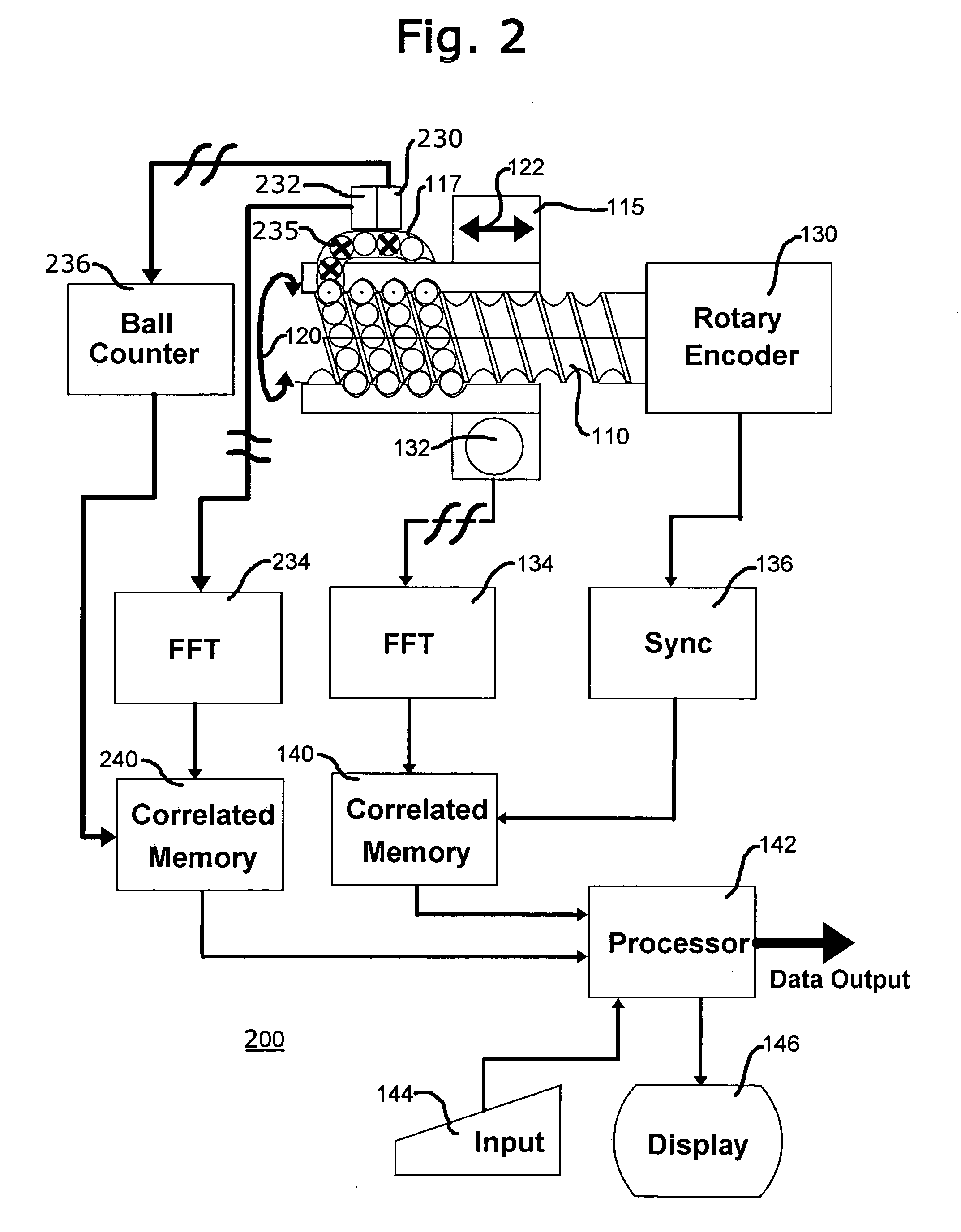
[0092]FIG. 1 is a schematic and function block representation of an annunciation arrangement 100 for a ball screw actuator. As shown in this figure, a screw shaft 110 is configured to engage a ball nut 115, and there is provided a ball recirculating system 117 that provides a multiplication of bearing balls (not specifically designated) in the interface between the screw shaft and the ball nut. As screw shaft 110 is rotated, illustratively in the direction of torque arrow 120, ball nut 115 is urged in the linear direction in accordance with bidirectional arrow 122.

[0093]In this embodiment of the invention, screw shaft 110 is coupled to a rotary encoder 130 that issues electrical signals that correspond to the angular position of the screw shaft. There is additionally provided in this specific illustrative embodiment of the invention a vibration transducer 132 that is shown to be directly coupled to the ball nut. Vibration transducer 132 receives acoustic or vibrational or displaceme...


PUM


Abstract

A system for announcing failure of a mechanically actuated arrangement employs a first coupler arrangement that couples an actuator to a structural element that is desired to be controlled, and a first force sensor is coupled to the first coupler arrangement. The first coupler arrangement and the first force sensor constitute a primary load path. Similarly, a second coupler arrangement is coupled to the actuator to the structural element and constitutes a secondary load path. Changes in the forces experienced by one or both of first and second force sensors are monitored by a controller / monitor system. A connector has a screw shaft in the primary load path and a preloaded tie rod in the secondary load path. Axial forces are generated by a drive motor, which can include a ball screw arrangement. Operating impulses generated by the ball screw arrangement are monitored during a predetermined interval of operation.

Description

RELATIONSHIP TO OTHER APPLICATION[0001]This application is a continuation-in-part patent application that claims the benefit of Provisional Patent Application Ser. No. 60 / 785,080, filed Mar. 23, 2006, and U.S. patent application Ser. No. 11 / 728,214, filed Mar. 23, 2007, now issued on Apr. 29, 2008 as U.S. Pat. No. 7,366,590, and claims the benefit of U.S. Ser. No. 12 / 150,174, filed Mar. 29, 2008, the disclosures of which are incorporated herein by reference.BACKGROUND OF THE INVENTION[0002]1. Field of the Invention[0003]This invention relates generally to methods of annunciating impending failure and failure in actuators and drive train components, as well as aircraft control systems.[0004]2. Description of the Prior Art[0005]There are present in the prior art a variety of vibration test systems that enable vibration analysis of operating mechanical systems to determine machine conditions and operating characteristics. In some of these known systems, a handheld device has an associa...

Claims


Application Information

Patent Timeline
30 Sep 2010
Publication
US20100250047A1
IPC
G06F19/00
CPC
B60T17/221; Y02T50/44; B64C13/28; B60W2050/146; Y02T50/40
Inventors
BALASU, MITCHELL GABRIEL MIRCEA; MONSANTO, RAPHAEL A.