Refrigeration apparatus

a technology of refrigerating apparatus and heat source, which is applied in the direction of refrigeration components, mechanical apparatus, lighting and heating apparatus, etc., can solve the problems of difficult to achieve high operating efficiency, large heat radiation loss of heat exchanger, and the difference in temperature between the refrigerant, etc., to suppress the reduction of defrosting capacity, reduce the density of refrigerant drawn into the second-stage compression element, and keep the defrosting capacity from being reduced

Active Publication Date: 2010-10-07
DAIKIN IND LTD
View PDF25 Cites 23 Cited by
  • Summary
  • Abstract
  • Description
  • Claims
  • Application Information

AI Technical Summary

Benefits of technology

[0010]In response to this problem, with this refrigeration apparatus, refrigerant is prevented from flowing to the intercooler by using the intercooler bypass tube after the defrosting of the intercooler has been completed, whereby the temperature of the refrigerant drawn into the second-stage compression element is kept from being reduced, and as a result, the temperature of the refrigerant discharged from the compression mechanism is kept from being reduced and the defrosting capacity of the heat source-side heat exchanger is kept from being reduced as well.
[0011]However, the temperature of the refrigerant drawn into the second-stage compression element increases rapidly when the refrigerant is not allowed to flow to the intercooler using the intercooler bypass tube after the defrosting of the intercooler has been completed. Therefore, the density of the refrigerant drawn into the second-stage compression element is reduced and the flow rate of the refrigerant drawn into the second-stage compression element tends to be lower. Accordingly, there is a risk that sufficient effect cannot be obtained for suppressing the reduction in defrosting capacity of the heat source-side heat exchanger in the balance between the effect of increasing the defrosting capacity by preventing the release of heat from the intercooler to the exterior and the effect of reducing the defrosting capacity by reducing the flow rate of refrigerant that flows through the heat source-side heat exchanger.
[0012]In view of the above, with this refrigeration apparatus, not only the refrigerant not allowed to flow to the intercooler by using the intercooler bypass tube, but a control is also performed so that the opening degree of the second-stage injection valve is increased, whereby the heat from the intercooler is prevented from being released to the exterior, the refrigerant sent from the heat source-side heat exchanger to the usage-side heat exchanger is returned to the second-stage compression element, the flow rate of the refrigerant that flows through the heat source-side heat exchanger is increased, and the loss of defrosting capability of the heat source-side heat exchanger is reduced. Also, the flow rate of the refrigerant that flows through the usage-side heat exchanger can be reduced.
[0013]With this refrigeration apparatus, a loss of defrosting capacity can be reduced when the reverse cycle defrosting operation is carried out. A drop in temperature on the usage side when the reverse cycle defrosting operation is carried out can be suppressed.

Problems solved by technology

As a result, since the refrigerant discharged from the second-stage compression element of the compressor has a high temperature, there is a large difference in temperature between the refrigerant and the water or air as a cooling source in the outdoor heat exchanger functioning as a refrigerant cooler, and the outdoor heat exchanger has much heat radiation loss, which poses a problem in making it difficult to achieve a high operating efficiency.
With this refrigeration apparatus, there is a danger of frost deposits forming in the intercooler in cases in which a heat exchanger whose heat source is air is used as the intercooler and the intercooler is integrated with a heat source-side heat exchanger whose heat source is air.

Method used


Image

  • Refrigeration apparatus
  • Refrigeration apparatus
  • Refrigeration apparatus

Examples


modification 1

(3) Modification 1

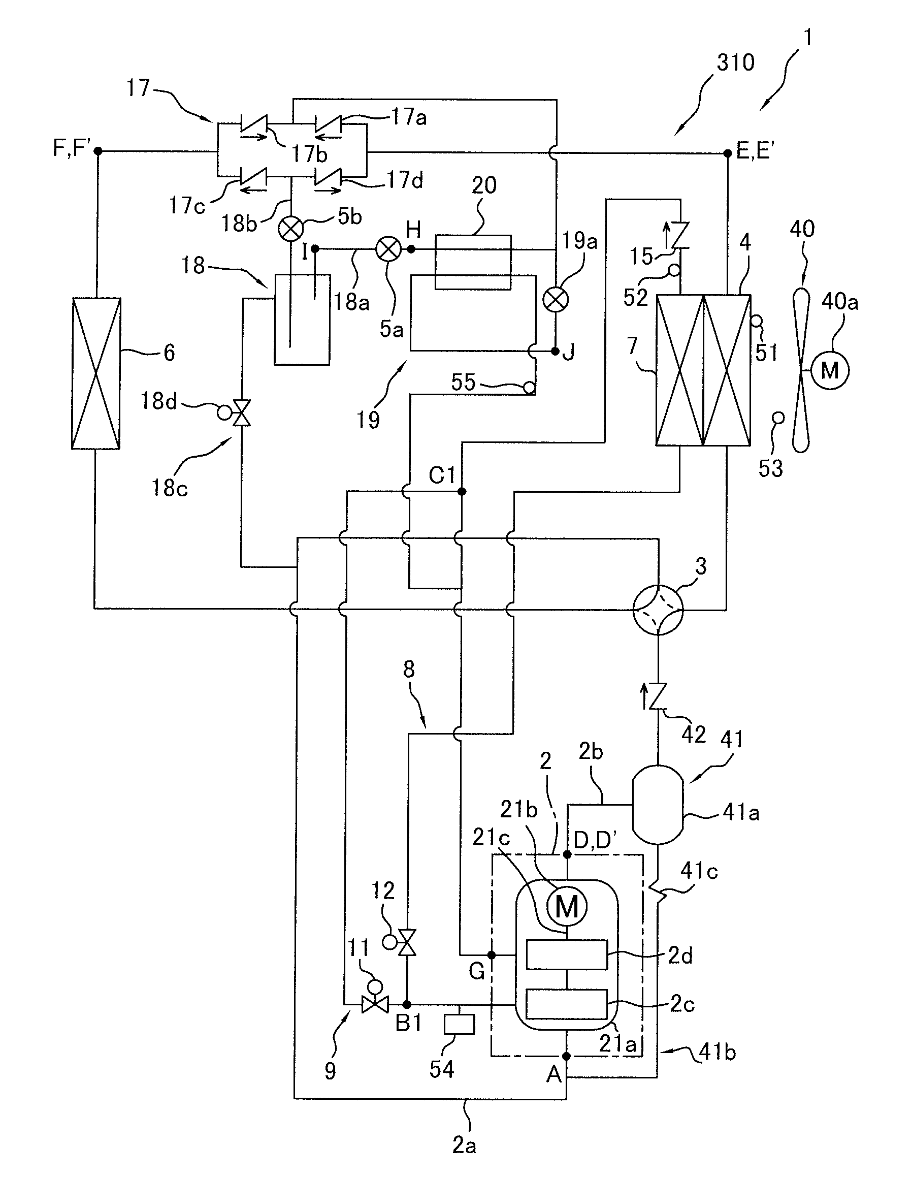
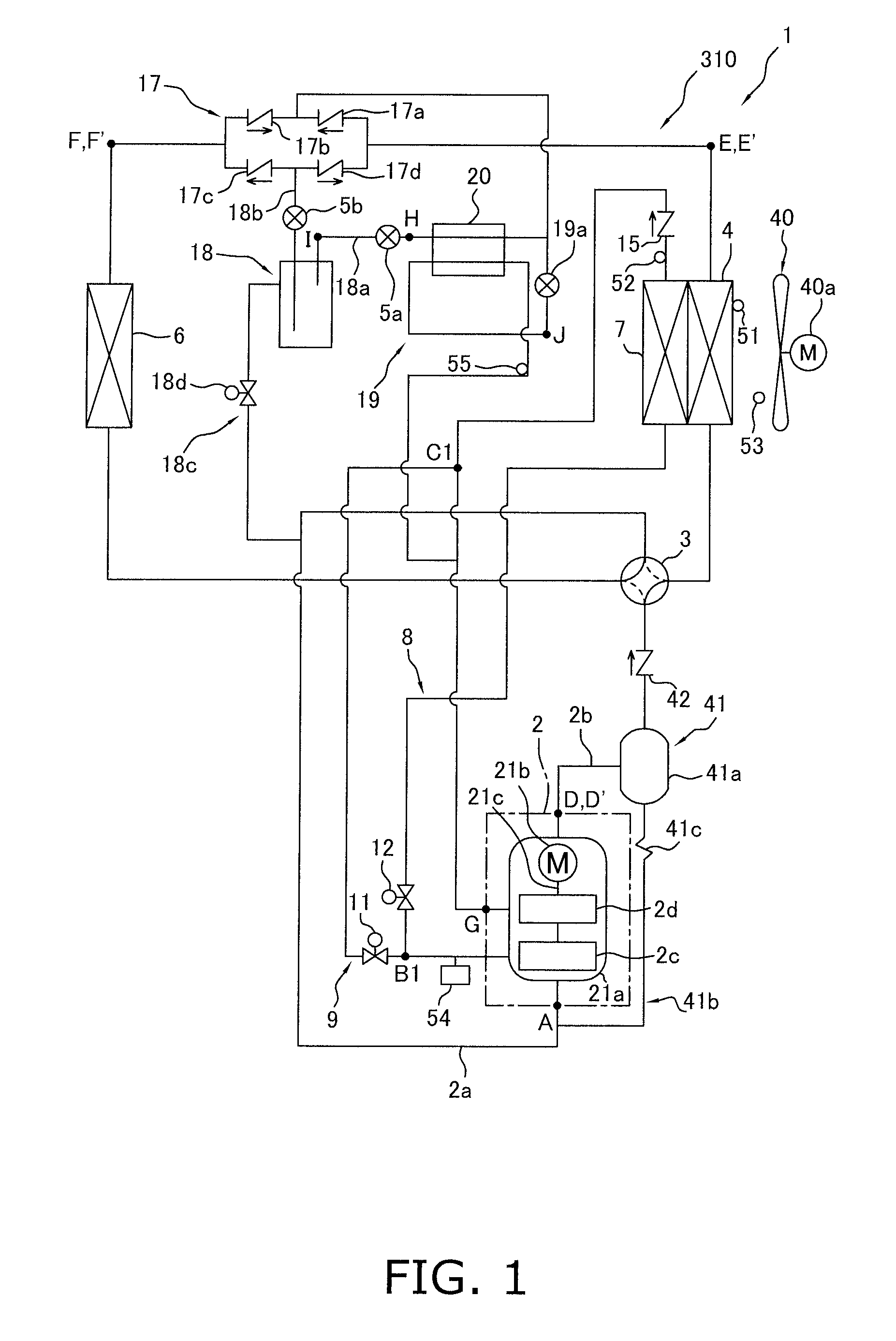
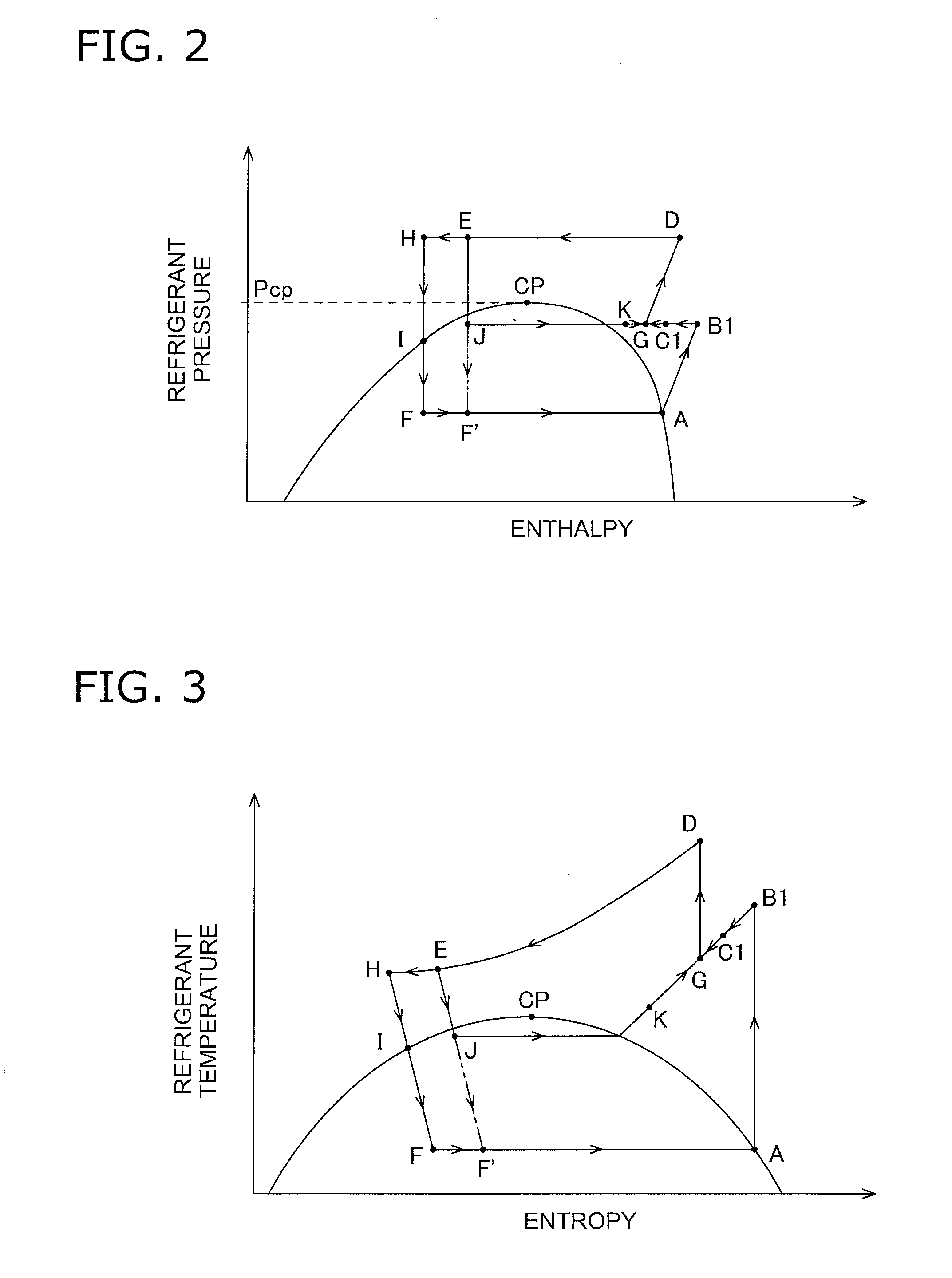
[0098]In the defrosting operation in the present embodiment described above, although only temporarily until defrosting of the intercooler 7 is complete, the refrigerant flowing through the intercooler 7 condenses and the refrigerant drawn into the compression element 2d becomes wet, presenting a risk that wet compression will occur in the second-stage compression element 2d and the compression mechanism 2 will be overloaded.

[0099]In view of this, in the present modification, as shown in FIG. 9, in cases in which it is detected in step S7 that the refrigerant has condensed in the refrigerant flowing through the intercooler 7, intake wet prevention control is performed in step S8 for reducing the flow rate of refrigerant returned to the second-stage compression element 2d via the second-stage injection tube 19.

[0100]The decision of whether or not the refrigerant has condensed in the refrigerant flowing through the intercooler 7 in step S7 is based on the degree of s...

modification 2

(4) Modification 2

[0102]In the above-described embodiment and modifications thereof, a two-stage compression-type compression mechanism 2 is configured from the single compressor 21 having a single-shaft two-stage compression structure, wherein two compression elements 2c, 2d are provided and refrigerant discharged from the first-stage compression element is sequentially compressed in the second-stage compression element, but another possible option is to configure a compression mechanism 2 having a two-stage compression structure by connecting two compressors in series, each of which compressors having a single-stage compression structure in which one compression element is rotatably driven by one compressor drive motor, as shown in FIG. 11, for example.

[0103]The compression mechanism 2 has a compressor 22 and a compressor 23. The compressor 22 has a hermetic structure in which a casing 22a houses a compressor drive motor 22b, a drive shaft 22c, and a compression element 2c. The co...

modification 3

(5) Modification 3

[0113]The refrigerant circuit 310 (see FIG. 1) and the refrigerant circuit 410 (see FIG. 12) in the embodiment and modifications described above have configurations in which one usage-side heat exchanger 6 is connected, but alternatively may have configurations in which a plurality of usage-side heat exchangers 6 is connected and these usage-side heat exchangers 6 can be started and stopped individually.

[0114]For example, the refrigerant circuit 310 (FIG. 1) which uses a two-stage compression-type compression mechanism 2 may be fashioned into a refrigerant circuit 510 in which two usage-side heat exchangers 6 are connected, usage-side expansion mechanisms 5c are provided corresponding to the ends of the usage-side heat exchangers 6 on the sides facing the bridge circuit 17, the receiver outlet expansion mechanism 5b previously provided to the receiver outlet tube 18b is omitted, and a bridge outlet expansion mechanism 5d is provided instead of the outlet non-return...


PUM


Abstract

A refrigeration apparatus uses a refrigerant that operates in a supercritical range. The refrigeration apparatus includes a compression mechanism, a heat source-side heat exchanger, an expansion mechanism, a usage-side heat exchanger, a switching mechanism, an intercooler, a bypass tube, and an injection tube. The switching mechanism is configured to switch between cooling and heating operation states. When the switching mechanism is switched to the cooling operation state to allow refrigerant to flow to the heat source-side heat exchanger and a reverse cycle defrosting operation for defrosting the heat source-side heat exchanger is performed, the refrigerant is caused to flow to the heat source-side heat exchanger, the intercooler and the injection tube. After the defrosting of the intercooler is detected as being complete, the bypass tube is used so as to ensure that the refrigerant does not flow to the intercooler and the injection valve is controlled so that the opening degree is increased.

Description

TECHNICAL FIELD[0001]The present invention relates to a refrigeration apparatus, and particularly relates to a refrigeration apparatus which has a refrigerant circuit configured to be capable of switching between a cooling operation and a heating operation and which performs a multistage compression refrigeration cycle by using a refrigerant that operates in a supercritical range.BACKGROUND ART[0002]As one conventional example of a refrigeration apparatus which has a refrigerant circuit configured to be capable of switching between a cooling operation and a heating operation and which performs a multistage compression refrigeration cycle by using a refrigerant that operates in a supercritical range, Patent Document 1 discloses an air-conditioning apparatus which has a refrigerant circuit configured to be capable of switching between an air-cooling operation and an air-warming operation and which performs a two-stage compression refrigeration cycle by using carbon dioxide as a refrig...

Claims


Application Information

Patent Timeline
Patent Type & Authority Applications(United States)
IPC IPC(8): F25B39/02
CPCF25B1/10F25B9/008F25B13/00F25B2309/061F25B2400/23F25B2313/02741F25B2400/075F25B2400/13F25B2313/0272F25B47/02F25B41/30
Inventor YOSHIMI, ATSUSHIFUJIMOTO, SHUJI
Owner DAIKIN IND LTD
Why Eureka
Try Eureka