

Acoustic transducer and image generation apparatus
a transducer and image technology, applied in the direction of instruments, catheters, specific gravity measurements, etc., can solve the problem that the resolution of the parametric signal is inferior in the depth direction, and achieve the effect of improving the resolution of the parametric signal
- Summary
- Abstract
- Description
- Claims
- Application Information
AI Technical Summary
Benefits of technology
Problems solved by technology
Method used
Image

Examples
first embodiment
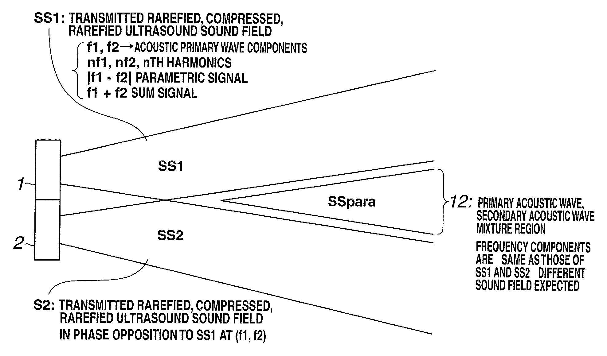
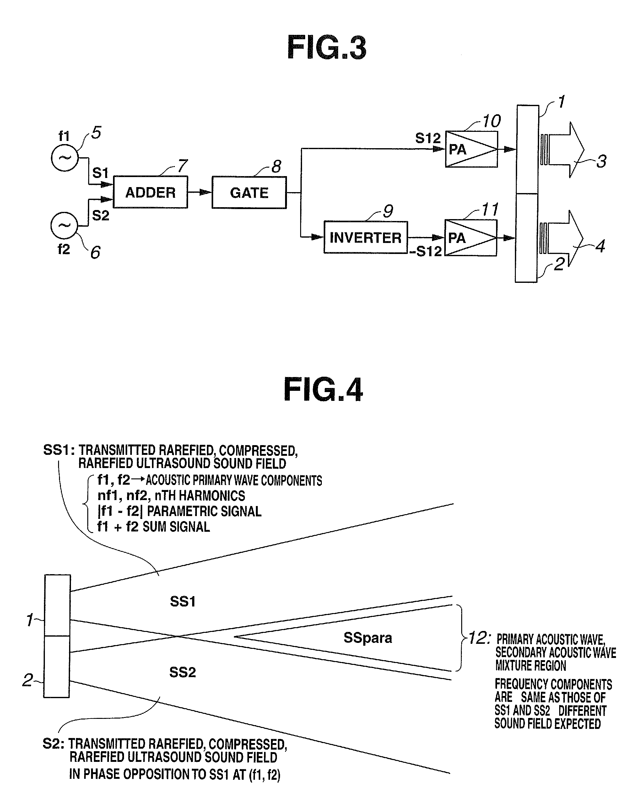
[0052]A first embodiment of the present invention will be described. A transmitting portion which transmits an acoustic primary wave having two frequency components will first be described.
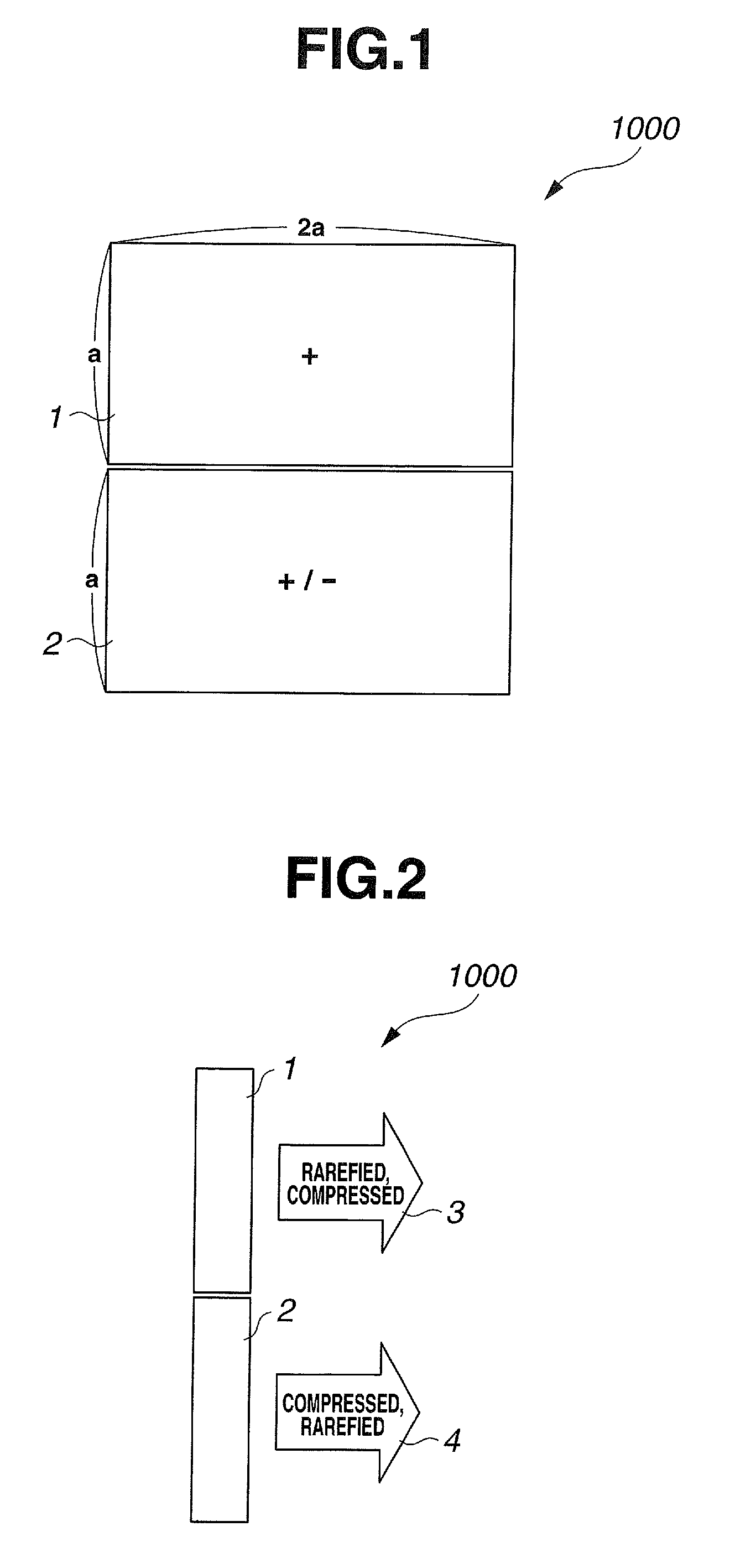
[0053]FIGS. 1 and 2 are diagrams for explaining the basic structure of a transmitting portion of an acoustic transducer according to the present embodiment. FIG. 1 is a plan view of the transmitting portion of the acoustic transducer according to the present embodiment. FIG. 2 is a side view for explaining the state of a side surface of the transmitting portion of the acoustic transducer and the state of acoustic waves according to the present embodiment.
[0054]As shown in FIG. 1, a transmitting portion 1000, which is a transducer, has regions for transmitting including a pair of acoustic transducers (also referred to as “transducer” below) 1 and 2 disposed adjacent to each other. The two transducers 1 and 2 constitute the transmitting portion 1000 of the parametric acoustic transducer. In the pres...
second embodiment
[0134]A second embodiment of the present invention will be described.
[0135]In the above-described first embodiment, thickness longitudinal vibration and bending vibration are utilized in the transmitting portion and in the receiving portion, respectively. The present embodiment differs from the first embodiment in that bending vibration is used in each of the transmitting portion and the receiving portion.
[0136]FIG. 19 is a cross-sectional view showing the structure of a parametric acoustic transducer according to the present embodiment. A transmitting and receiving parametric acoustic transducer 88 is configured by including a transmitting portion 88A and a receiving portion 88B. This parametric acoustic transducer 88 is of such a structure as to be suitably applied to a case where the frequency of an acoustic primary wave is low, for example, 100 kHz or less.
[0137]The transmitting portion 88A is configured by including two piezoelectric bimorphs 75 and 84.
[0138]The bimorphs 75 and...
third embodiment
[0188]A third embodiment of the present invention will be described.
[0189]In the above-described first and second embodiments, a piezoelectric transducer is used in each of the transmitting and receiving portions. The present embodiment differs from the first and second embodiments in its using an electrostatic transducer in each of transmitting and receiving portions.
[0190]This electrostatic transducer includes transmitting and receiving of ultrasound by using a cMUT (capacitive Micromachined Ultrasonic Transducer) made by using a MEMS technique. In the present embodiment, a parametric transmitting and receiving device with a cMUT used in an ultrasound endoscope system will be described.
[0191]FIG. 23 is a diagram of the configuration of a parametric signal transmitting and receiving system using an electrostatic transducer as a transducer according to the present embodiment. FIG. 24 is a plan view of the electrostatic transducer. FIG. 25 is a cross-sectional view of the electrostat...
PUM
| Property | Measurement | Unit |
|---|---|---|
| distance | aaaaa | aaaaa |
| frequencies | aaaaa | aaaaa |
| frequencies | aaaaa | aaaaa |
Abstract
Description
Claims
Application Information