Fluid heating system

a technology of heating system and fluid, applied in the field of fluid heating system, to achieve the effect of facilitating the unidirectional travel direction of domestic hot water flow and facilitating the operation of fluid flow

Active Publication Date: 2010-10-07
DONGO KENNETH A +1
View PDF35 Cites 50 Cited by
  • Summary
  • Abstract
  • Description
  • Claims
  • Application Information

AI Technical Summary

Benefits of technology

[0016]In an embodiment of the invention the fluid heat exchange circuit is set up to naturally avoid steam generation—as in natural passage of warmer or heated water to cooler water zones with a pump being preferably provided to facilitate operational control of fluid flow in the fluid circuit. Hence, with this embodiment there is avoided the need for steam accommodation equipment in the fluid flow circuit.
[0017]In an embodiment of the invention the flow circuit is set up to avoid the presence of check valves and the like relative to the flow of fluid through the system as there is featured a one way arrangement flow which avoids the concern for reverse flow in the system (again the flow circuit is set up such that advantage is taken of the hot-cold fluid thermodynamics to facilitate a unidirectional domestic hot water flow travel direction without the need for check-valves).

Problems solved by technology

There is lacking in the art a domestic hot water heater system that takes advantage of the characteristics of regulated heat supply heating devices as in a pellet stove relative to a heat absorption component as in a domestic hot water unit (e.g., a 20 to 90 gallon domestic hot water tank) via an efficient circulation loop and flow control system.
There is also lacking in the prior art a hot water heater system that provides for rapid retrofitting of a preexisting hot water heater system, without substantial deviation of that system, for use with a pellet stove or the like, as well as increasing the options as to a multitude of different fuel sources for a domestic hot water tank or the like.

Method used


Image

  • Fluid heating system
  • Fluid heating system
  • Fluid heating system

Examples


Embodiment Construction

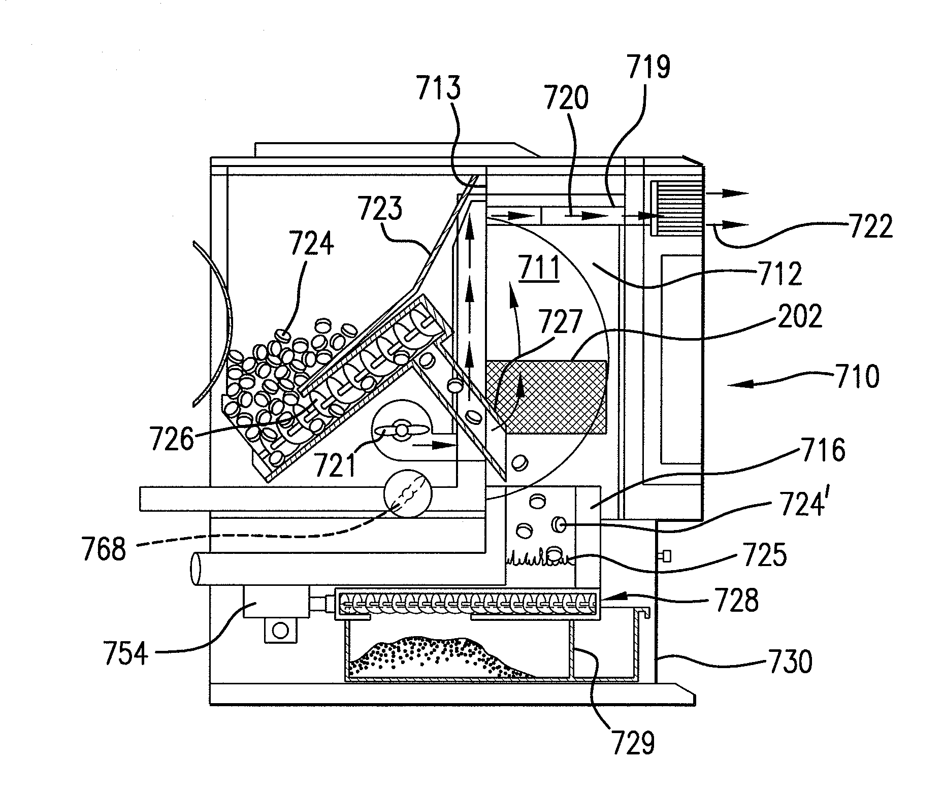
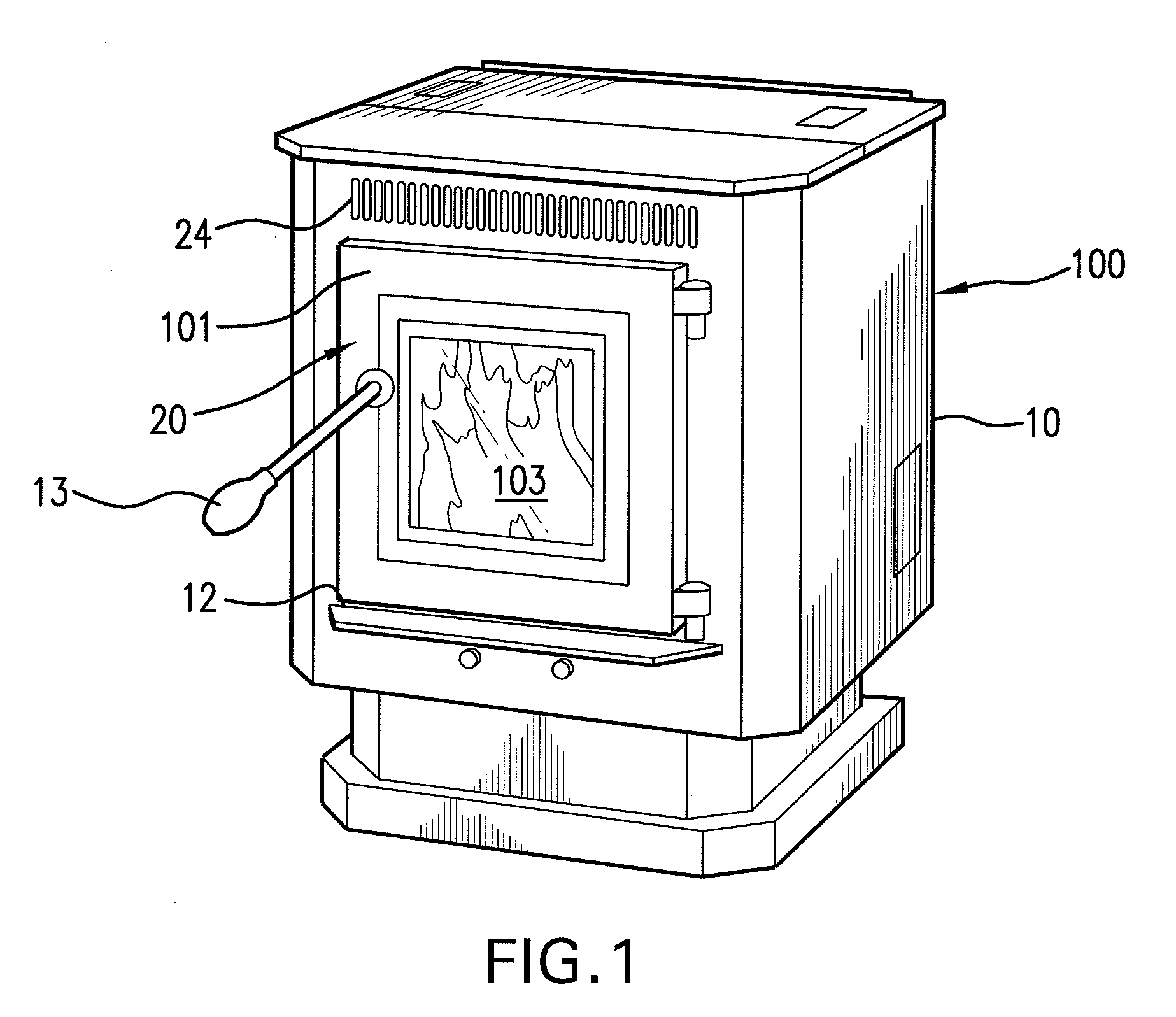
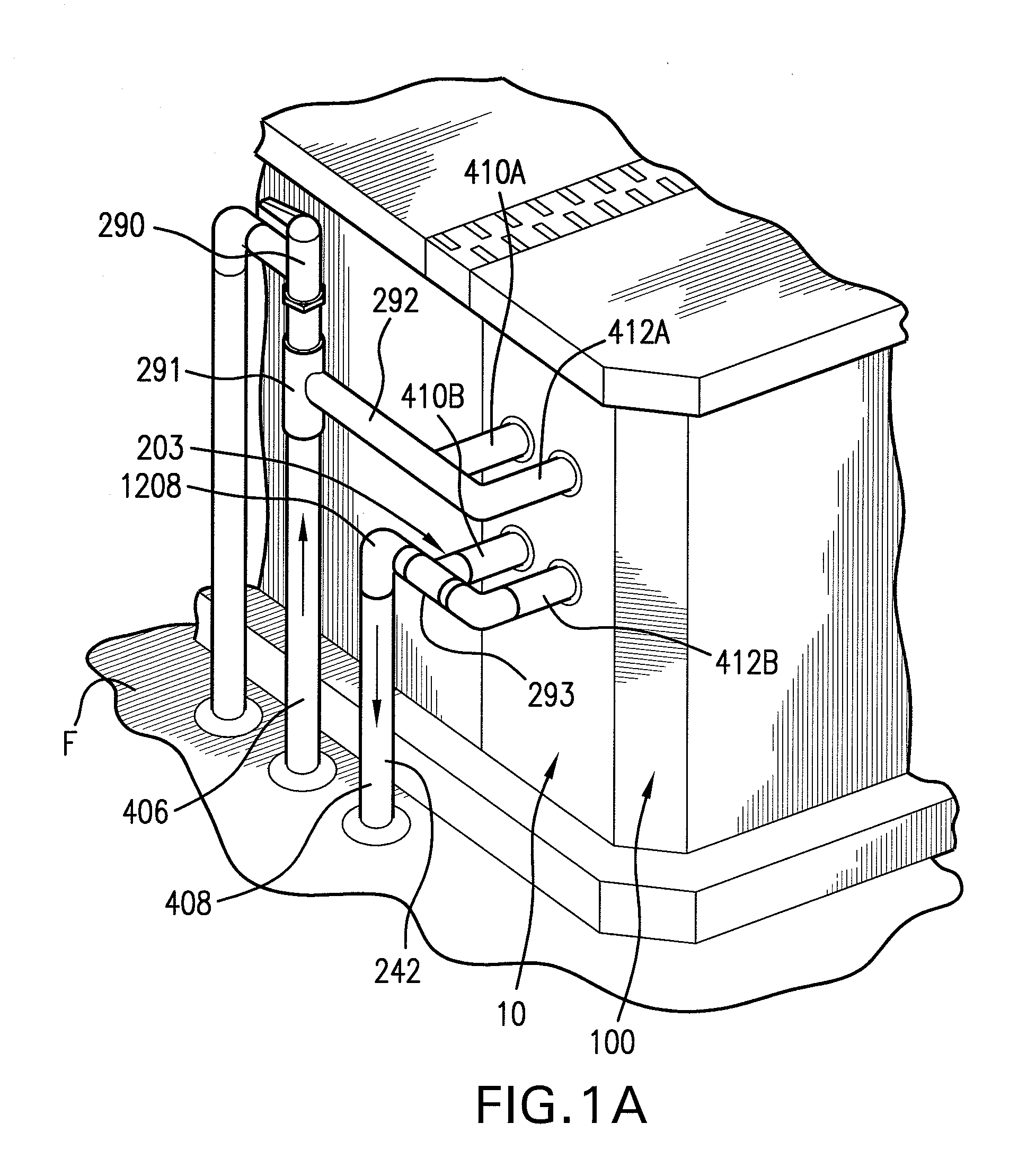
[0033]FIG. 1 shows a perspective view of heater device 100, which is preferably in the form of a pellet stove providing heat supply means in an embodiment of the present invention. Heat supply means 100 provides a source of heat energy to the below described fluid flow heat exchange circuit 200 (see FIG. 5). The combination of heat supply means 100 and fluid flow circuit 200 provides fluid heating system 300. While a variety of heat supply means 100 can be utilized in embodiments of the fluid heating system 300 of the present invention, a heat supply means that features an automated and controllable supply of relatively consistent geometrically shaped solid biomass fuel units to a burner location such as a pellet stove is preferred. Also, the solid fuel is preferably of a relatively consistent constitution in the material forming those fuel units as in processed sawdust or other waste material biomass (e.g., consistency from pellet-to-pellet of either a relatively unitary type of so...


PUM

PropertyMeasurementUnit
temperatureaaaaaaaaaa
temperaturesaaaaaaaaaa
temperatureaaaaaaaaaa

Abstract

A fluid heat exchange system with a fluid flow circuit having a heat exchange fluid flow loop, a heat absorption component (as in a domestic hot water tank inclusive of small commercial use tanks as in tanks of 20 to 120 gallons), a heat exchanger and preferably also a pump. A controlled and automated fuel supply source based heater (as in a pellet stove) is in heat passage communication with the said heat exchanger. A control unit triggers activation of the pump upon fluid in the heat absorption component reaching or dropping below a preset temperature, and the fluid flow circuit is arranged such that, during times of non-activation of the pump, fluid is free to flow in a unidirectional flow within the fluid circuit based on thermodynamic temperature differentials alone. A retrofitting of a domestic hot water tank is also featured preferably making use of preexisting drain and safety vent porting for in-feed and out-feed porting in the exchange loop side. Also, the flow circuit preferably is free of check valves and steam accommodation equipment.

Description

CROSS REFERENCE TO RELATED APPLICATION(S)[0001]This application claims the benefit of U.S. Provisional Application No. 61 / 202,569, filed Mar. 12, 2009 which application is incorporated herein by reference.FIELD OF INVENTION EXAMPLE[0002]Subject matter of the present invention is inclusive of a fluid heating system, with a preferred embodiment featuring a fluid heat exchange loop or fluid flow circuit which preferably receives heat from an automated or regulated fuel supplied heat source, as in a pellet stove, and that is designed to transfer heat derived from that heat source to a heat absorption component of the fluid flow circuit which is preferably in the form of a domestic hot water tank.BACKGROUND OF THE INVENTION[0003]Pellet burning heating devices are known such as those described in the following patent(s) and publications(s):[0004]Pellet stoves are often installed in residential homes as secondary environmental air heat sources and, in some instances, as a primary environme...

Claims


Application Information

Patent Timeline
Patent Type & Authority Applications(United States)
IPC IPC(8): F24H9/20F24H1/18F23K3/00B23P11/00
CPCF23B40/08Y10T29/49826F23N1/082F23N2025/19F24B1/024F24D3/10F24D3/1083F24D12/02F24D17/0031F24D19/1051F24D2200/067F24D2200/08F24H1/202F24H1/205F24H9/122F24H9/124F24H9/2057F24H2230/00F28D9/005F28D20/0034Y02B30/14F23K2203/202F23N2225/19Y02B30/00F24H9/13F24H9/133
Inventor DONGO, KENNETH A.CURRAN, TIMOTHY
Owner DONGO KENNETH A
Why Eureka
Try Eureka