Valve drive of an internal combustion engine

a technology of internal combustion engine and valve drive, which is applied in the direction of valve arrangement, machines/engines, mechanical equipment, etc., can solve the problems of rapid conflict between the length of the cam piece and the installation space available for the piece, and achieve the effect of convenient operation

Inactive Publication Date: 2010-10-07
SCHAEFFLER TECH AG & CO KG
View PDF14 Cites 44 Cited by
  • Summary
  • Abstract
  • Description
  • Claims
  • Application Information

AI Technical Summary

Benefits of technology

[0015]In addition, the two constructions named above allow a comparatively easily performed expansion of the stroke variability from two to three stages in that two activation elements are coupled selectively in the bidirectional axial links. This is disc

Problems solved by technology

Under consideration of various structural parameters of the internal combustion engine, in particular, the cylinder and gas-exchange valve spacing, the number and width of the cams, and also

Method used


Image

  • Valve drive of an internal combustion engine
  • Valve drive of an internal combustion engine
  • Valve drive of an internal combustion engine

Examples


Embodiment Construction

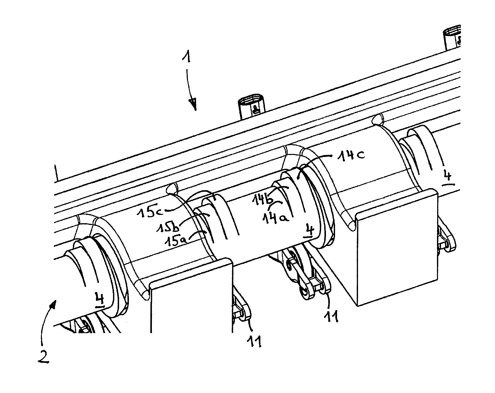
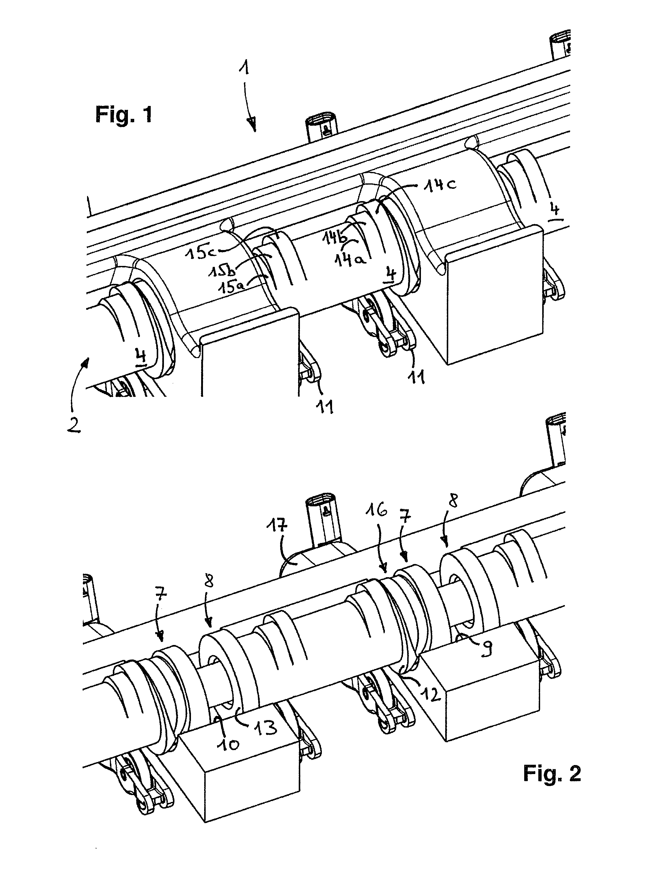
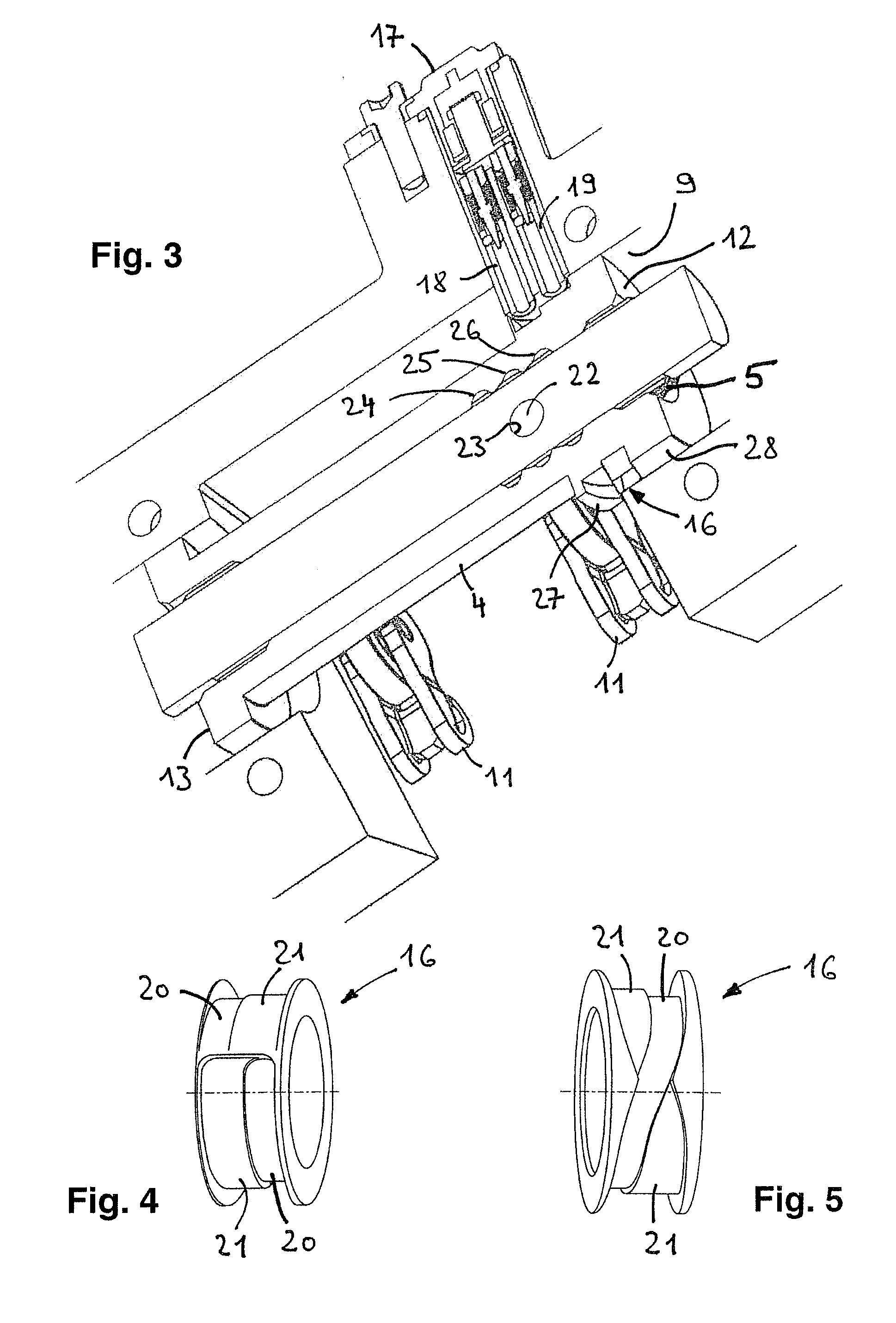
[0030]In FIGS. 1 to 3, a cutout section of a valve drive 1 of an internal combustion engine that is essential for understanding the invention is disclosed with stroke-variable gas-exchange valve activation and four-valve technology. A component that is central to the function of the valve drive 1 is a camshaft 2 that comprises a carrier shaft 3 and also cam pieces 4 that are arranged in a rotationally locked way on the carrier shaft and that can move between three axial positions—corresponding to the number of cylinders of the internal combustion engine. For the purpose of axial shifting, the carrier shaft 3 is provided with outer longitudinal teeth and each cam piece 4 is provided with corresponding inner longitudinal teeth. The teeth 5 and 6 can be seen in FIGS. 3 and 8. The intermediate spaces that can be seen between the axial end sections 7 and 8 allow the separate shifting of the cam pieces 4 in sync with the ignition sequence of the internal combustion engine into an adjacent...


PUM


Abstract

A valve drive (1, 1′) of an internal combustion engine with stroke-variable gas-exchange valve activation is provided. The valve drive includes a camshaft (2, 2′) with a carrier shaft (3) and a cam piece (4, 4′) that is arranged in a rotationally locked way on the carrier shaft and that can move between axial positions and that has a cam group of directly adjacent cams (14a-c, 15a-c) with different lobes and a groove-shaped axial link (16, 16′) and an activation element (18, 19) that can be coupled in the axial link for shifting the cam piece on the carrier shaft. The cam piece is provided with a bearing journal (12, 13, or 12′) on which the camshaft is supported in the radial direction at a camshaft bearing point (9, 10, or 9′) of the internal combustion engine. Here, the axial link is constructed overlapping with the camshaft bearing point on the bearing journal in the axial direction, and the activation element runs in the camshaft bearing point.

Description

CROSS-REFERENCE TO RELATED APPLICATIONS[0001]This application claims the benefit of German Patent Application No. 10 2009 016 463.4, filed Apr. 4, 2009, which is incorporated herein by reference as if fully set forth.[0002]1. Field of the Invention[0003]The invention relates to a valve drive of an internal combustion engine with stroke-variable gas-exchange valve activation. The valve drive comprises a camshaft with a carrier shaft and a cam piece that is arranged in a rotationally locked manner on the carrier shaft and that can move between axial positions and that has a cam group of directly adjacent cams with different lobes and a groove-shaped axial link extending on the outer periphery and an activation element that can be coupled in the axial link for shifting the cam piece on the carrier shaft. The cam piece is provided with a bearing journal on which the camshaft is supported in the radial direction at a camshaft bearing point of the internal combustion engine.[0004]2. Backg...

Claims


Application Information

Patent Timeline
IPC IPC(8): F01L1/34
CPCF01L1/047F01L13/0005F01L2013/0052F01L2001/0473F01L13/0036
Inventor ELENDT, HARALDNENDEL, ANDREAS
Owner SCHAEFFLER TECH AG & CO KG
Why Eureka
Try Eureka