Low concentrations of gas bubbles to hinder proppant settling

a proppant settling and low concentration technology, applied in fluid removal, chemistry apparatus and processes, borehole/well accessories, etc., can solve the problems of insufficient foam production and insufficient proppant settling rate, and achieve the effect of reducing proppant settling ra

Inactive Publication Date: 2010-10-07
CLEARWATER INT LLC
View PDF101 Cites 73 Cited by
  • Summary
  • Abstract
  • Description
  • Claims
  • Application Information

AI Technical Summary

Benefits of technology

[0008]Embodiments of the present invention provide a composition including a fracturing fluid including a proppant and a gas, where the proppant is present in an amount sufficient to prop open fractures introduced into a formation during fracturing and the gas is present in an amount sufficient to reduce a proppant settling rate in the composition. It is thought that the gas forms small bubbles in the fluid, which act to hinder proppant settling or to reduce the density of the proppant or to form micobubble coated particles in the composition, thereby reducing a proppant settling rate.
[0010]Embodiments of the present invention also provide a method for fracturing a well including the step of providing a frac fluid. Once the frac fluid has been prepared, injecting the fluid into a formation of an oil and / or gas well at a pressure, temperature and flow rate sufficient to cause or produce fractures in the formation, where the proppant is present in an amount sufficient to prop open fractures introduced into the formation during fracturing and where the gas is present in effective amount sufficient to reduce a proppant settling rate in the frac fluid by forming micro bubble coated proppant particles.

Problems solved by technology

If the fracturing fluid includes a proppant, then the method also includes the step of adding a gas to the frac fluid, where the proppant is present in an amount sufficient to prop open fractures introduced into a formation during fracturing and where the gas is introduced in an amount sufficient to reduce a proppant settling rate in the frac fluid, but insufficient to produce a foam.
If proppants added to the fracturing fluid after initial fracturing, then the method includes the step of adding a proppant and a gas to the fracturing fluid after initial fracturing, where the proppant is present in an amount sufficient to prop open fractures introduced into a formation during fracturing and where the gas is introduced in an amount sufficient to reduce a proppant settling rate in the frac fluid, but insufficient to produce a foam.

Method used


Image

  • Low concentrations of gas bubbles to hinder proppant settling
  • Low concentrations of gas bubbles to hinder proppant settling
  • Low concentrations of gas bubbles to hinder proppant settling

Examples


example 1

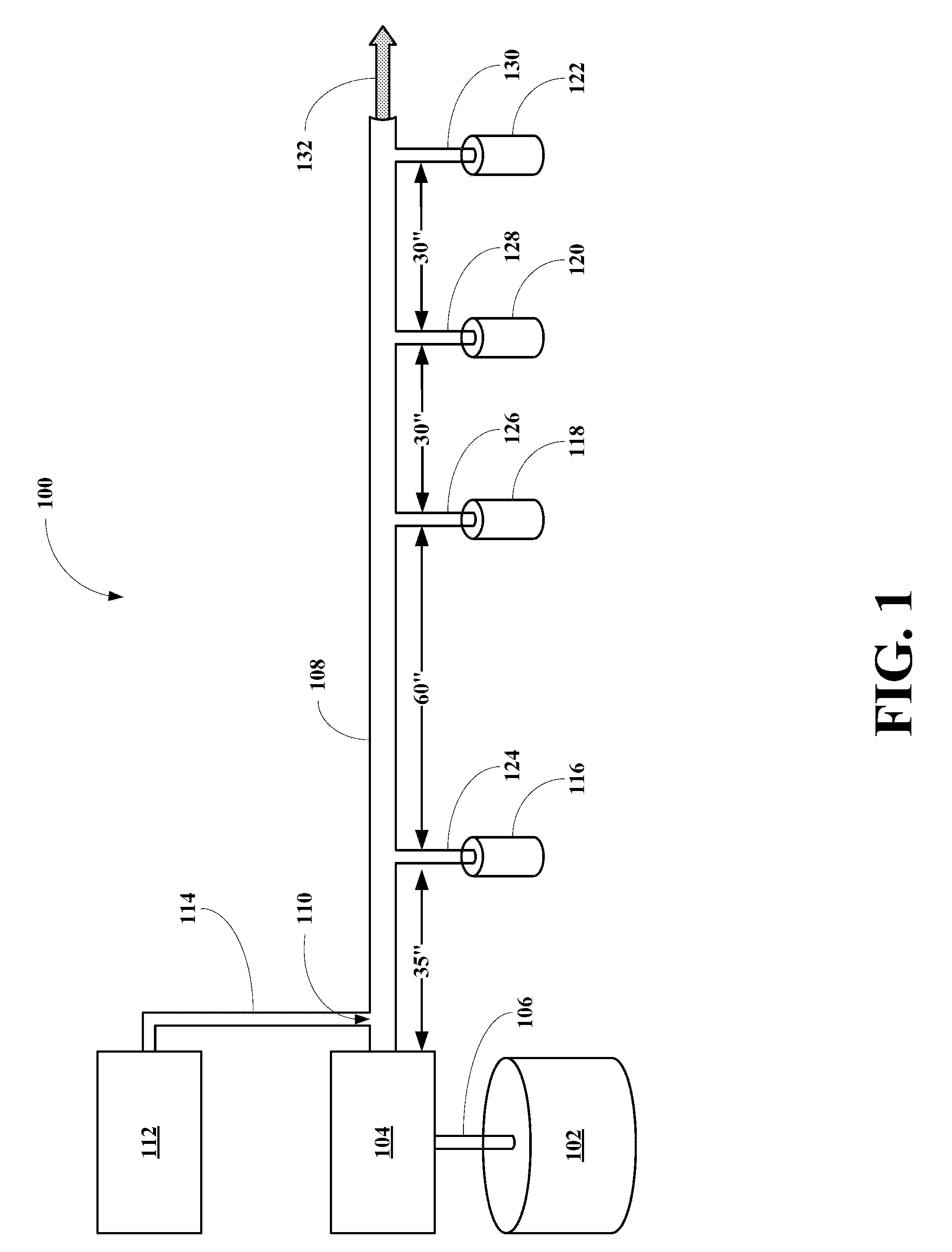
[0062]In this example, proppant settling rates were measured using a slick water fracturing fluid, where the fluid includes a proppant in the apparatus of FIG. 1. The proppant used was 20 / 40 sand in an amount of 0.5 lb / gal of the slick water fracturing fluid.

[0063]The slick water fracturing fluid including the sand was pumped by the pump 104 from its slurry tank 102 into the flow line 108 at flow rates between 1.42 gal / min and 1.31 gal / min. Air was used as the gas in this example and was supplied from a cylinder or unit 112 into the line 108 via the line 114 at flow rates between 0 gal / min and 0.120 gal / min, corresponding to a gas phase percentage between 0% and 9.16% gas. The settling rate at the four stations 116, 118, 120 and 122 were measured and are tabulated in Table 1.

TABLE 1Slick Water Fracturing Fluid Proppant Suspension TestFlow RateFlow RateSlick WaterTime to FillTime to FillTime to FillTime to FillAirFrac Fluid% GasStation 1Station 2Station 3Station 4Test #(gal / min)(gal / ...

example 2

[0070]In this example, proppant settling rates were measured using a guar gum fracturing fluid, where the fluid includes a proppant in the apparatus of FIG. 1. The proppant used was 20 / 40 sand in an amount of 0.5 lb / gal of the guar gum fracturing fluid.

[0071]The guar gum fracturing fluid including the sand was pumped by the pump 104 from its slurry tank 102 into the flow line 108 at flow rates between 1.32 gal / min and 1.21 gal / min. Air was used as the gas in this example and was supplied from a cylinder or unit 112 into the line 108 via the line 114 at flow rates between 0 gal / min and 0.123 gal / min, corresponding to a gas phase percentage between 0% and 10.17% gas. The settling rate at the four stations 116, 118, 120 and 122 were measured and are tabulated in Table 2.

TABLE 2Guar Gum Fracturing Fluid Proppant Suspension TestFlow RateFlow RateGuar GumTime to FillTime to FillTime to FillTime to FillAirFrac Fluid% GasStation 1Station 2Station 3Station 4Test #(gal / min)(gal / min)Phase(sec)...

example 3

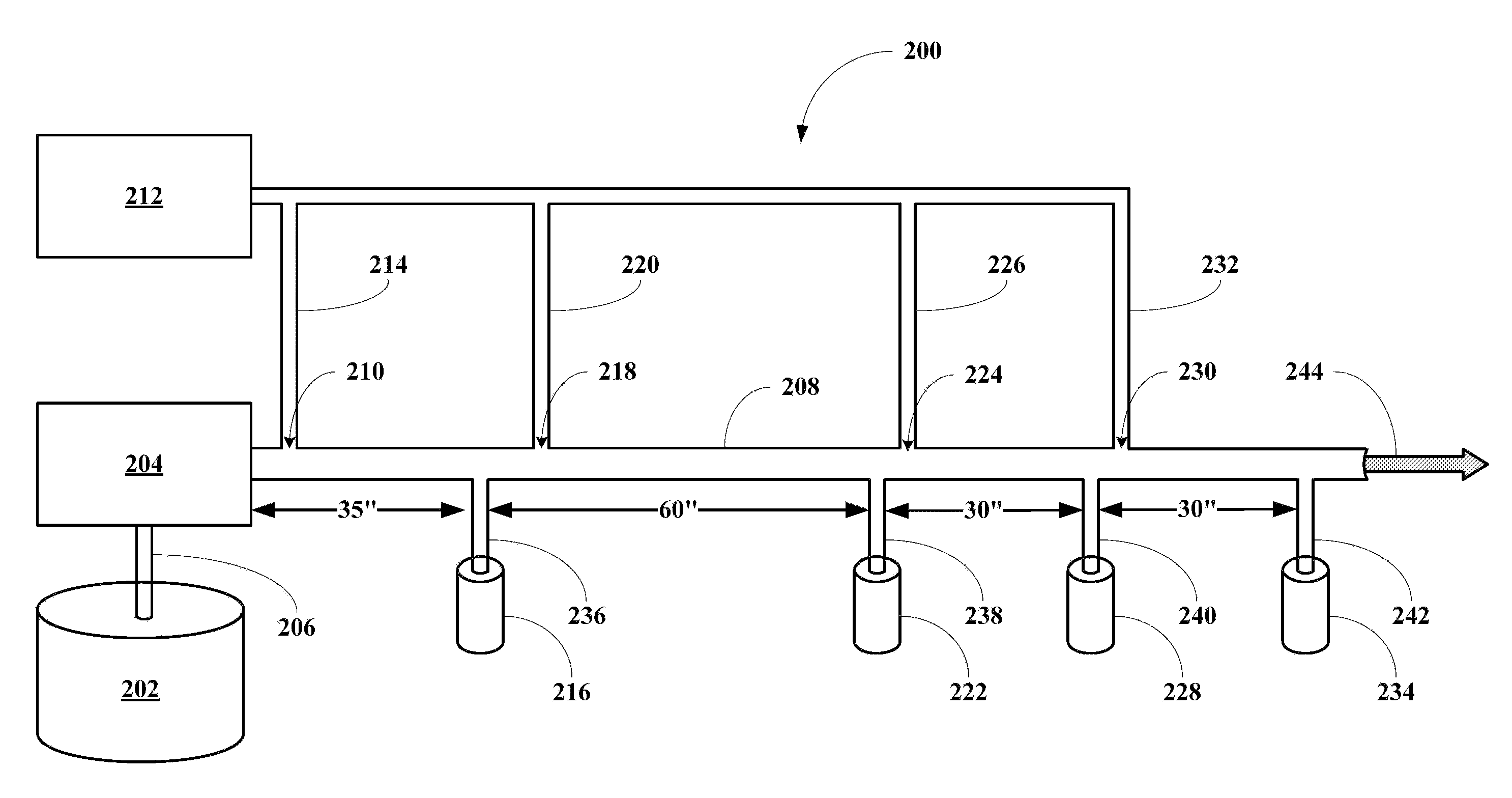
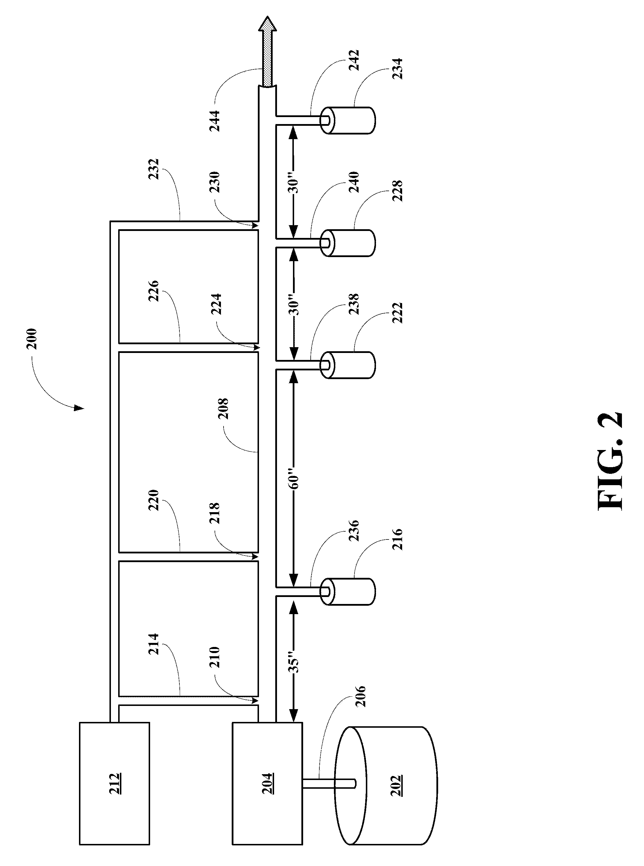
[0078]In this is a prophetic example, proppant settling rates are measured using a slick water fracturing fluid, where the fluid includes a proppant in the apparatus of FIG. 2. The proppant use is 20 / 40 sand in an amount of 0.5 lb / gal of the slick water fracturing fluid.

[0079]The slick water fracturing fluid including the sand is pumped by the pump 104 from its slurry tank 202 into the flow line 208 at flow rates between 1.42 gal / min and 1.31 gal / min. Air is used as the gas in this example and is supplied from a cylinder or unit 212 into the line 208 via the lines 214, 220, 226, and 232 at flow rates between 0 gal / min and 0.120 gal / min, corresponding to a gas phase percentage between 0% and 9.16% gas. The settling rate at the four stations 216, 222, 228 and 234 are measured and tabulated in Table 3.

TABLE 3Slick Water Fracturing Fluid Proppant Suspension TestFlow RateFlow RateSlick WaterTime to FillTime to FillTime to FillTime to FillAirFrac Fluid% GasStation 1Station 2Station 3Stati...


PUM

PropertyMeasurementUnit
volume fractionaaaaaaaaaa
sizeaaaaaaaaaa
volume fractionaaaaaaaaaa

Abstract

Methods are disclosed for reducing settling rates of proppants in fracturing fluids, where the method includes injection sufficient gas into the fluid to form bubbles that reduce proppant settling rates. Compositions including a proppants make buoyant with gas bubbles are also disclosed.

Description

BACKGROUND OF THE INVENTION[0001]1. Field of the Invention[0002]The present invention relates to a method for reducing proppant settling rates in fracturing fluids and to compositions and methods for using same.[0003]More particularly, the present invention relates to a method for reducing proppant settling rates in fracturing fluids, where the method involves the step of injecting an amount of a gas below an amount sufficient to form a stable foam into the fracturing fluid, but sufficient to reduce a settling rate of proppants in the fracturing fluid including a proppant. The invention also relates to a composition including a fracturing fluid including proppants and an amount of a gas sufficient to reduce a settling rate of the proppant, yet insufficient to form a stable foam. The invention also relates to a method for fracturing a formation using a composition of this invention.[0004]2. Description of the Related Art[0005]Historically, the oil service industry deals with proppant...

Claims


Application Information

Patent Timeline
Patent Type & Authority Applications(United States)
IPC IPC(8): E21B43/267E21B43/26C09K8/70
CPCE21B43/267C09K8/70
Inventor EKSTRAND, BARRYZAMORA, FRANKKAKADJIAN, SARKIS R.
Owner CLEARWATER INT LLC
Why Eureka
Try Eureka