Auxiliary Drive Device

a technology of auxiliary drive and drive shaft, which is applied in the direction of electric vehicles, propulsion by batteries/cells, electric energy vehicles, etc., can solve the problems of higher emissions and fuel costs, energy security risks, and harmful emissions

Inactive Publication Date: 2010-10-07
BIBEAU ERIC +1
View PDF25 Cites 45 Cited by
  • Summary
  • Abstract
  • Description
  • Claims
  • Application Information

AI Technical Summary

Benefits of technology

[0013]By providing an auxiliary drive which can be coupled in fixed relation to a vehicle chassis, the direction of driving force of the auxiliary drive remains aligned with the forward movement of the vehicle to provide additional force as required during peak demands of the engine of the vehicle in a configuration which is much more stable than the prior art. Even when no trailer is present, by mounting the auxiliary drive wheel and motor directly to the chassis of the vehicle in fixed relation thereto, auxiliary drive can be provided to the vehicle when there is increased demand on the engine of the vehicle during acceleration, for example. This also allows the vehicle to operate using grid electricity as another source of power.

Problems solved by technology

Current motorised vehicles rely heavily on non-renewable fossil fuels which are relatively expensive, supply will peak, cause energy security risks, produce harmful emissions, and contribute to the increase in greenhouse gases that result in climate change.
However, these motorised vehicles with relatively large engine size are less efficient leading to higher emissions and fuel costs.
The motorised vehicle will thus operate less efficiently overall resulting in poorer fuel mileage.
The configuration of the drive only permits its use on a large semi-trailer as no means are provided for use on other vehicles when extra demand is required on the engine but no trailer is present.
Furthermore the auxiliary drive unit is positioned at the rear trailing end of the trailer to be pivotal with the trailer relative to the vehicle so that negotiating a turn with the towing vehicle can cause instability in the trailer due to the direction of auxiliary drive being misaligned with the forward movement of the vehicle.
The auxiliary drive has no use when the trailer is coupled to a towing vehicle and thus provides no solution to the problem of increased engine demand when towing a trailer.

Method used


Image

  • Auxiliary Drive Device
  • Auxiliary Drive Device
  • Auxiliary Drive Device

Examples


Embodiment Construction

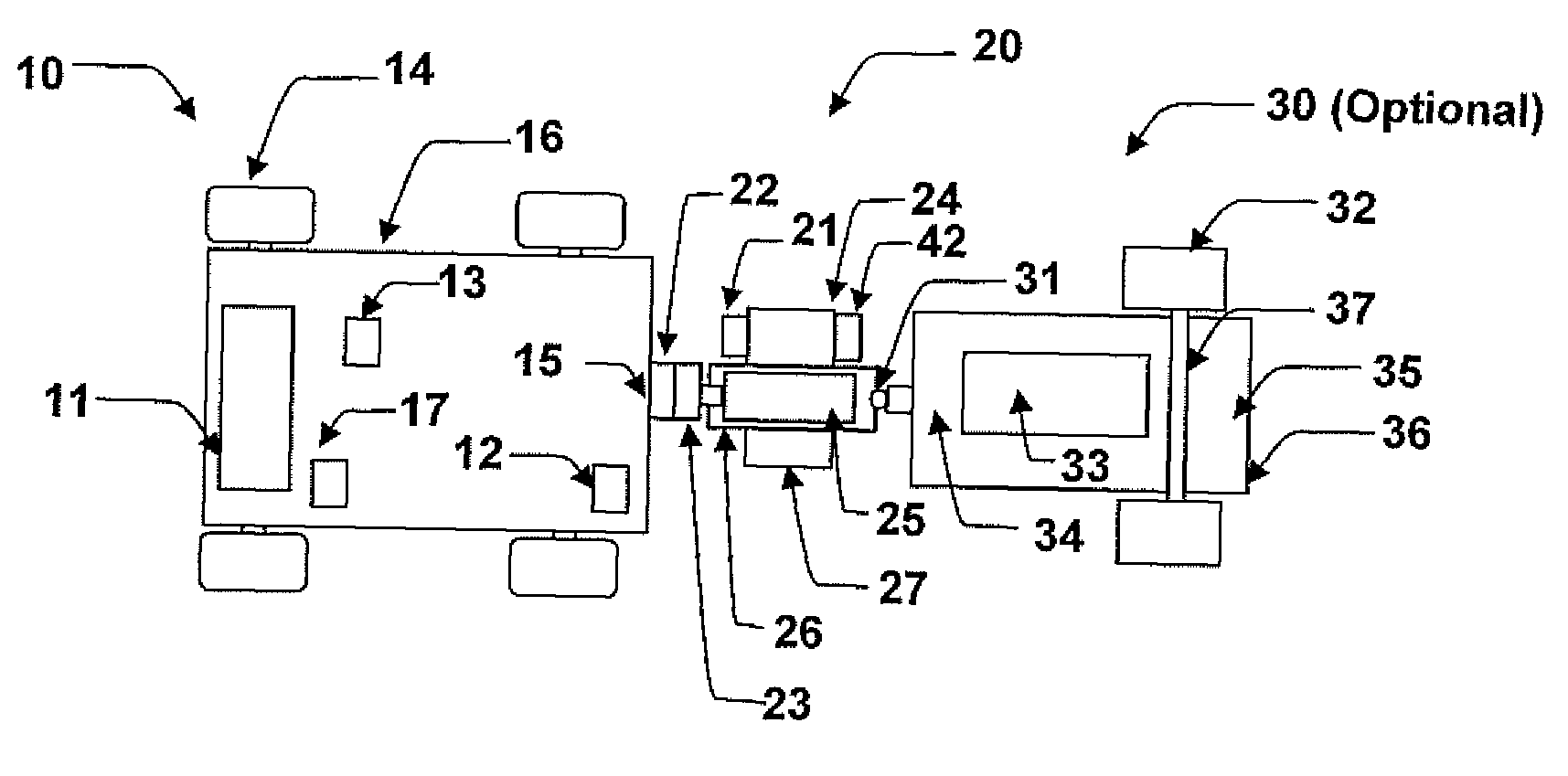
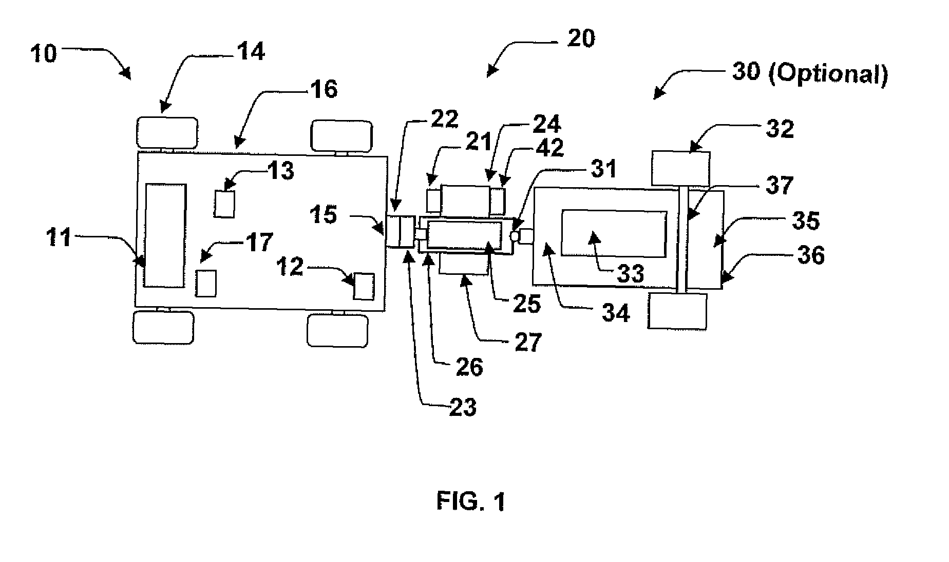
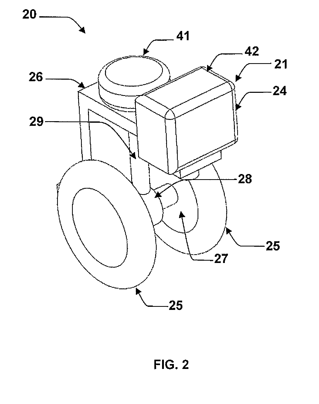
[0081]Referring to the accompanying FIGS. 1 to 4 there is illustrated an auxiliary drive device generally indicated by reference numeral 20. The auxiliary drive device 20 is particularly suited for use with vehicle 10 to supplement the drive power of the vehicle in a first instance, and to optionally provide motive drive to a trailer 30 and a load 33 when optionally connected in a second instance. The auxiliary drive device 20 allows hybrid through the road by extracting power from a primary motor 11 of the vehicle and allows regenerative braking of the vehicle 10 and optionally the trailer 30 and the load 33 when connected.

[0082]The vehicle 10 with which the auxiliary drive device 20 is used includes a vehicle chassis 16 supported for rolling movement along the ground on respective wheels 14. A primary motor 11 is supported on the vehicle chassis 16 of the vehicle 10 to drive the rolling movement of the vehicle along the ground. In some embodiments the vehicle chassis includes a hi...


PUM


Abstract

An auxiliary drive device is disclosed that connects to a motorised vehicle to supplement the drive of the motorised vehicle depending on the speed and acceleration of the motorised vehicle by using stored energy. The auxiliary drive device obtains energy by regenerative braking when the motorised vehicle decelerates, extracting energy from the motorised vehicle by using hybrid through the road, and by recharging from the power grid. The auxiliary drive device uses the stored energy to supplement the drive of the motorised vehicle depending on the motorised vehicle speed, acceleration, drive cycle, the amount of energy stored, and if the motorised vehicle is towing a load. A controller maximizes fuel savings and towing performance of the motorised vehicle. The controller determines when the auxiliary drive device needs to provide the mortised vehicle with power assistance, resistance via braking and when to conserve the stored energy for later use.

Description

[0001]This application claims the benefit under 35 U.S.C. 119(e) of U.S. provisional application Ser. No. 60 / 986,848, filed Nov. 9, 2007. The present application is based on and claims priority from this application, the disclosure of which is expressly incorporated herein by reference.FIELD OF THE INVENTION[0002]The present invention relates to an auxiliary drive device for connection to a vehicle having a primary motor to supplement the drive of the primary motor, for example to allow hybridization of the motorised vehicle, to permit the storage and use of grid power, and to provide power assistance when towing a trailer, and further relates to an auxiliary drive device which is separable from the vehicle with a trailer to provide drive to the trailer when the trailer is not attached to a towing vehicle and also relates to an auxiliary power unit to power electrical loads for stationary and mobile applications.BACKGROUND[0003]The use of motorised vehicles for transportation has be...

Claims


Application Information

Patent Timeline
Patent Type & Authority Applications(United States)
IPC IPC(8): B62D59/04
CPCB60K6/26B60K6/48B60L11/1801B60L2200/28B60L2210/20Y02T10/725B62D59/02B62D63/08Y02T10/6221Y02T10/6269Y02T10/7005B60Y2200/145B60L50/53Y02T10/62Y02T10/70Y02T10/72
Inventor BIBEAU, ERICGHORBANI, REZA
Owner BIBEAU ERIC
Why Eureka
Try Eureka