

Method and Arrangement to Adjust an Air-Gap
- Summary
- Abstract
- Description
- Claims
- Application Information
AI Technical Summary
Benefits of technology
Problems solved by technology
Method used
Image

Examples
Embodiment Construction
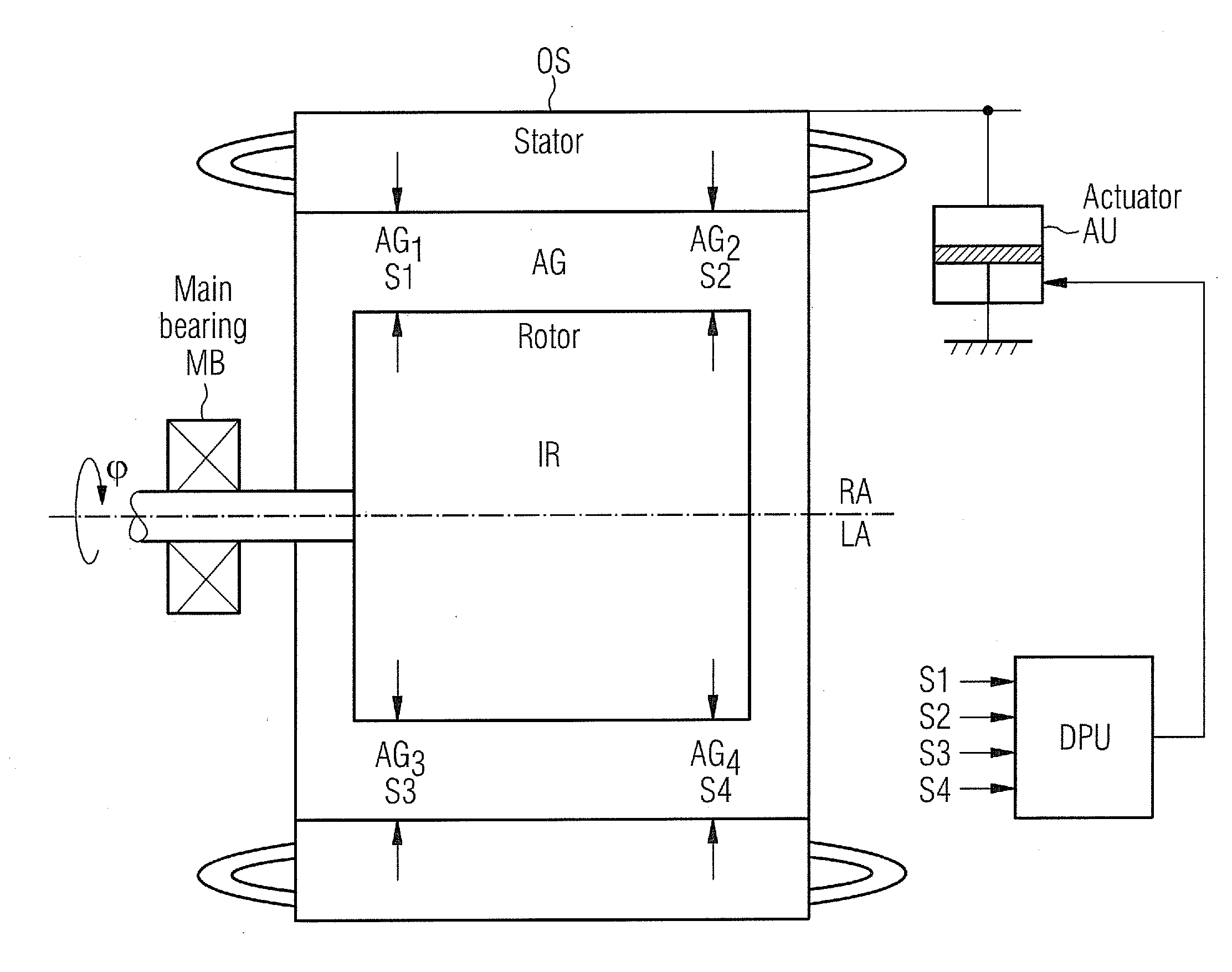
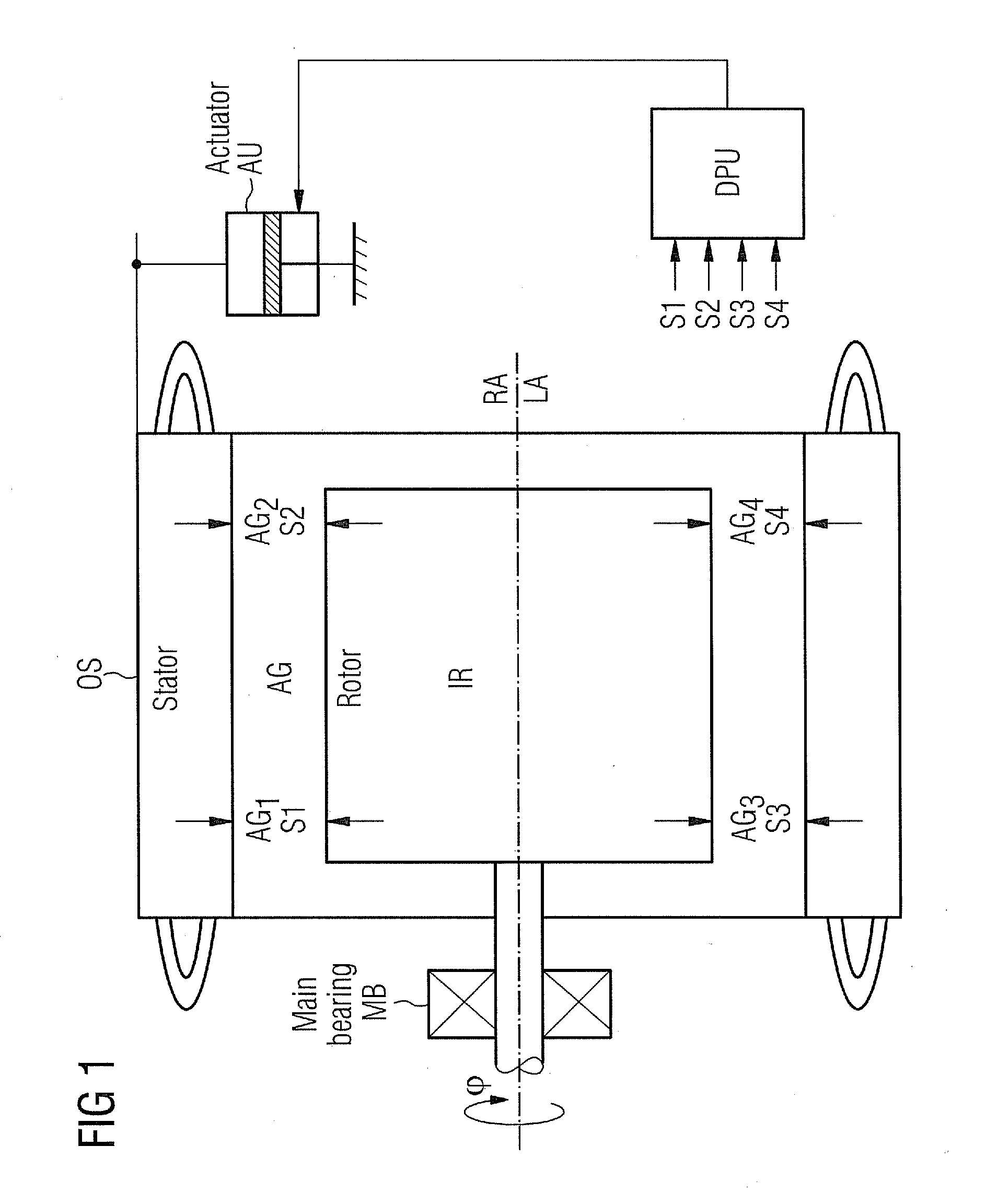
[0033]FIG. 1 shows the invention used at an electrical machine with an outer stator OS as static part and an inner rotor IR as movable part.
[0034]The inner rotor IR rotates around a dedicated rotary axis RA, so a rotation in relation to the outer stator OS is achieved.
[0035]The rotation is allowed by help of so called main-bearings MB, where one is shown here.
[0036]An air-gap AG is located between the inner rotor IR and the outer stator OS, while the spacing AG1, AG2, AG3, AG4 of the air-gap AG between the inner rotor IR and the outer stator OS is measured at e.g. four positions by help of sensors S1 to S4.
[0037]It is also possible to use a rotating line sensor, which is measuring the entire air-gap.
[0038]It is also possible to use only one single sensor or even a number of sensors, which might be positioned in a line to measure the entire air-gap.
[0039]The outer stator OS shows a longitudinal axis LA, which is aligned to the rotary axis RA. In this drawing both axes show the same p...
PUM
 Abstract
Description
Claims
Application Information