
Pfc converter having two-level output voltage without voltage undershooting

a converter and output voltage technology, applied in the field of power factor correction converters, can solve the problems of low conversion efficiency, power loss of rectifier, waste of redundant power consumption on power switch switching loss, etc., and achieve the effect of avoiding a faulty operation

Active Publication Date: 2010-10-07
SEMICON COMPONENTS IND LLC
View PDF6 Cites 36 Cited by
  • Summary
  • Abstract
  • Description
  • Claims
  • Application Information

AI Technical Summary

Benefits of technology

[0024]According to another aspect of the present invention, a turbo current is used to eliminate a first voltage undershooting of the bulk voltage of the PFC converter at the transient that the bulk voltage decreases to arrive at a second level from a first level.
[0025]According to another aspect of the present invention, the line-effective voltage and the voltage-loop error signal are utilized to avoid a faulty operation of the bulk voltage of the PFC converter.
[0026]According to another aspect of the present invention, the voltage-loop error signal is maximized to eliminate a second voltage undershooting of the bulk voltage of the PFC converter at the transient that the bulk voltage starts to increase toward the first level from the second level.

Problems solved by technology

This lowers the conversion efficiency because a level of the bulk voltage VBULK to sufficiently supply the load is only 300VDC, for example, a second level.
Redundant power consumption is therefore wasted on the switching loss of the power switch 70 and the power loss of the rectifier 30.
This causes insufficient energy transmission to maintain the bulk voltage VBULK at the second level VBULK2.
This might cause a brownout condition for the PWM circuit 60.
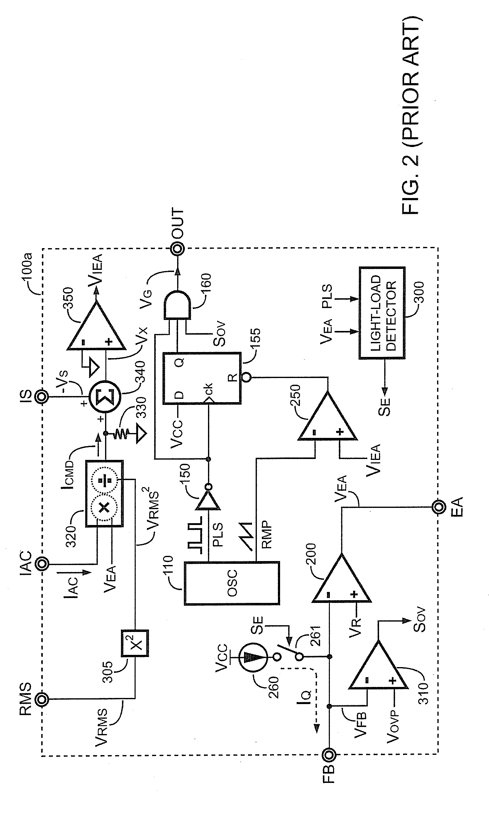
Even though the related art as mentioned above solves the problem of redundant power consumption under light-load condition for the PFC converter, it still fails to overcome the voltage undershooting problem.

Method used


Image

  • Pfc converter having two-level output voltage without voltage undershooting
  • Pfc converter having two-level output voltage without voltage undershooting
  • Pfc converter having two-level output voltage without voltage undershooting

Examples


Embodiment Construction

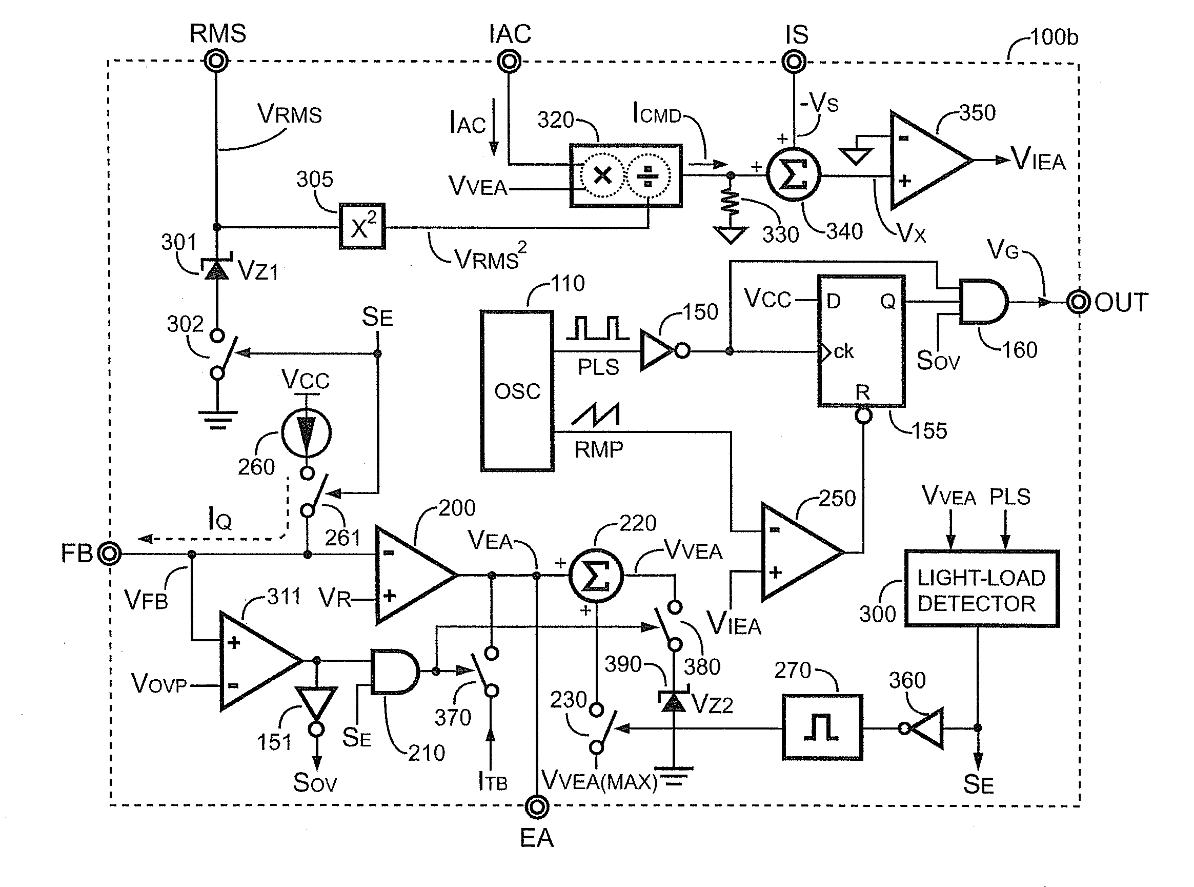
[0036]Referring now to the drawings wherein the contents are for purposes of illustrating the embodiment of the invention only and not for purposes of limiting the same. Components having similar or identical functions as aforementioned to the related art will be assigned the same numbers for following descriptions.

[0037]FIG. 4 shows a switching controller 100b of a PFC converter in FIG. 1 according to an embodiment of the present invention. The switching controller 100b comprises a switching-control circuit, a current-command circuit, a programmable feedback circuit, a modulator, an over-voltage detection circuit, a light-load detection circuit, a line-voltage terminal RMS, a line-current terminal IAC, a current-sense terminal IS, a compensation terminal EA, a feedback terminal FB, and an output terminal OUT.

[0038]As shown in FIG. 4, the current-command circuit comprises a square circuit 305, a multiplier-divider 320, a resistor 330, an adder 340, a current-loop error amplifier 350...


PUM


Abstract

A switching controller for a PFC converter is provided. The switching controller comprises a switching-control circuit, a current-command circuit, a programmable feedback circuit, a modulator, an over-voltage detection circuit, and a light-load detection circuit. The switching controller is capable of regulating a bulk voltage of the PFC converter at different levels in response to load conditions of the PFC converter. A turbo current eliminates a first voltage undershooting of the bulk voltage at the transient that the bulk voltage decreases to arrive at a second level from a first level. A voltage-loop error signal is maximized to eliminate a second voltage undershooting of the bulk voltage at the transient that the bulk voltage starts to increase toward the first level from the second level.

Description

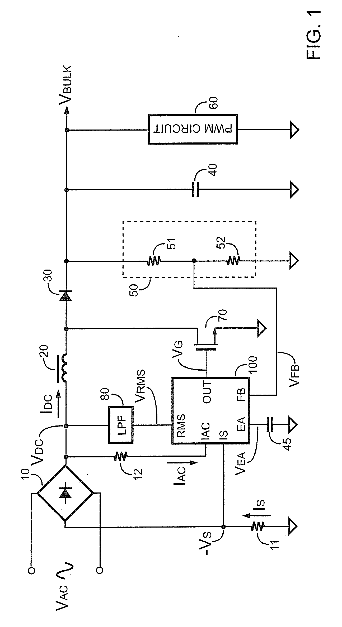
BACKGROUND OF THE INVENTION[0001]1. Field of the Invention[0002]The present invention relates to power factor correction (PFC) converters, and more particularly, relates to a switching controller of PFC converters.[0003]2. Description of Related Art[0004]FIG. 1 schematically shows a circuit of a PFC converter. A bridge rectifier 10 rectifies a line voltage VAC into an input voltage VDC. The input voltage VDC is supplied to an inductor 20. A low-pass filter 80 receives the input voltage VDC to generate a line-effective voltage VRMS. A rectifier 30 is connected between the inductor 20 and an output of the PFC converter. A bulk capacitor 40 is coupled between the output of the PFC converter and a ground reference to provide a bulk voltage VBULK. The bulk voltage VBULK is a boosted voltage which is higher than the input voltage VDC. The bulk voltage VBULK is used to provide power to a load of the PFC converter, for example, a PWM circuit 60. A power switch 70 coupled to a joint of the i...

Claims


Application Information

Patent Timeline
Patent Type & Authority Applications(United States)
IPC IPC(8): G05F1/10
CPCH02M1/4225Y02B70/16Y02B70/126H02M2001/0032Y02B70/10H02M1/0032
Inventor CHEN, CHENG-SUNGHSU, CHIEN-TSUN
Owner SEMICON COMPONENTS IND LLC
Learn More