Radio frequency coil arrangement for high field magnetic resonance imaging with optimized transmit and receive efficiency for a specified region of interest, and related system and method

Active Publication Date: 2010-10-07
NEW YORK UNIVERSITY
View PDF9 Cites 13 Cited by
  • Summary
  • Abstract
  • Description
  • Claims
  • Application Information

AI Technical Summary

Benefits of technology

[0013]Additionally, the angle can be selected to be, e.g., greater than zero degrees and less than or equal to about 60 degrees, and/or greater than or equal to about 10 degrees and less than or equal to about 50 degrees, such as about 30 degrees, for example. Further, certain exemplary coil arrangements according to the present disclosure can include at least one geometrically decoupled element so as to extend the coverage of imaging.
[0014]The elements can be configured to provide a phase between the ele

Problems solved by technology

A significant challenge for magnetic resonance (MR) imaging at fields above 3 Tesla can be the relative lack of available radio frequency (RF) coils.
In addition, the design of RF coils for high field can be complicated since, at the higher RF frequencies, there may be a more complex interaction of the RF excitation field with the sample.
This can lead to an excitation inhomogeneity due to wavelength effects and complex twisted B1+ and B1− profiles which differ significantly from those seen at low field.
Even at low fields, this coil design suffers from transmit and receive profiles which are steeply reduced with depth into the sample.
With increasing fie

Method used


Image

  • Radio frequency coil arrangement for high field magnetic resonance imaging with optimized transmit and receive efficiency for a specified region of interest, and related system and method
  • Radio frequency coil arrangement for high field magnetic resonance imaging with optimized transmit and receive efficiency for a specified region of interest, and related system and method
  • Radio frequency coil arrangement for high field magnetic resonance imaging with optimized transmit and receive efficiency for a specified region of interest, and related system and method

Examples


Embodiment Construction

[0007]Indeed, one of the objects of certain exemplary embodiments of the present disclosure can be to address the exemplary problems described herein above, and / or to overcome the exemplary deficiencies commonly associated with the prior art as, e.g., described herein.

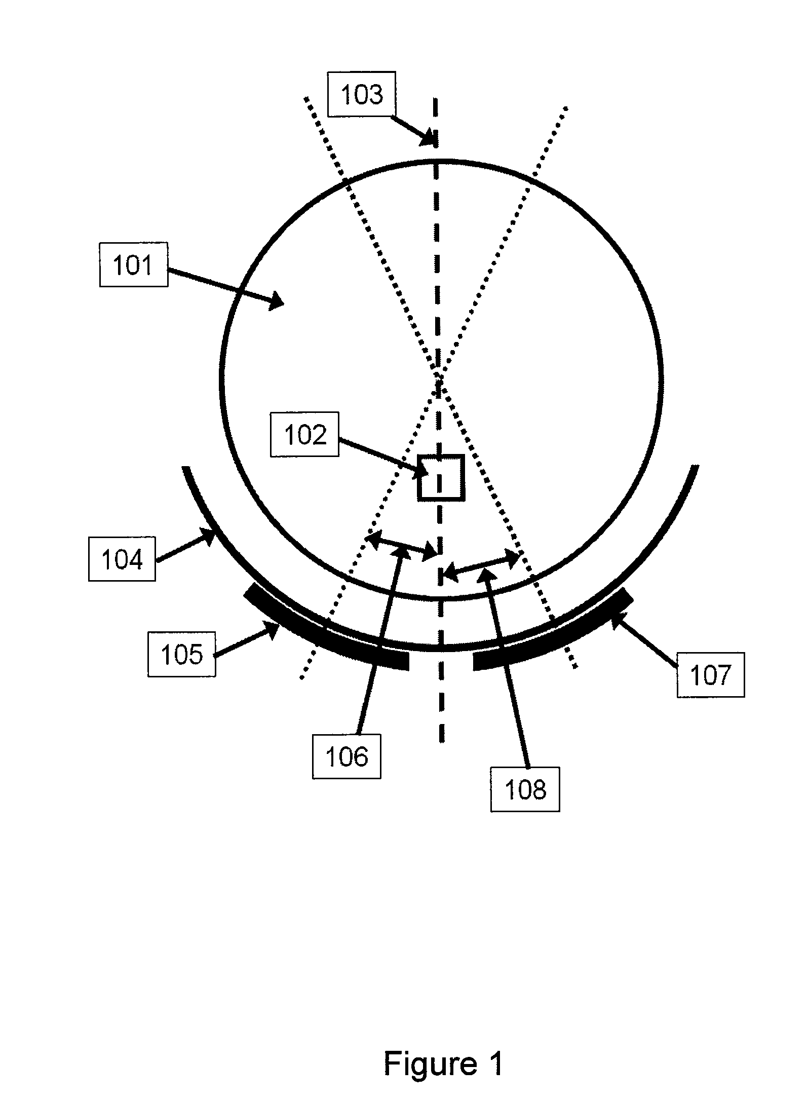
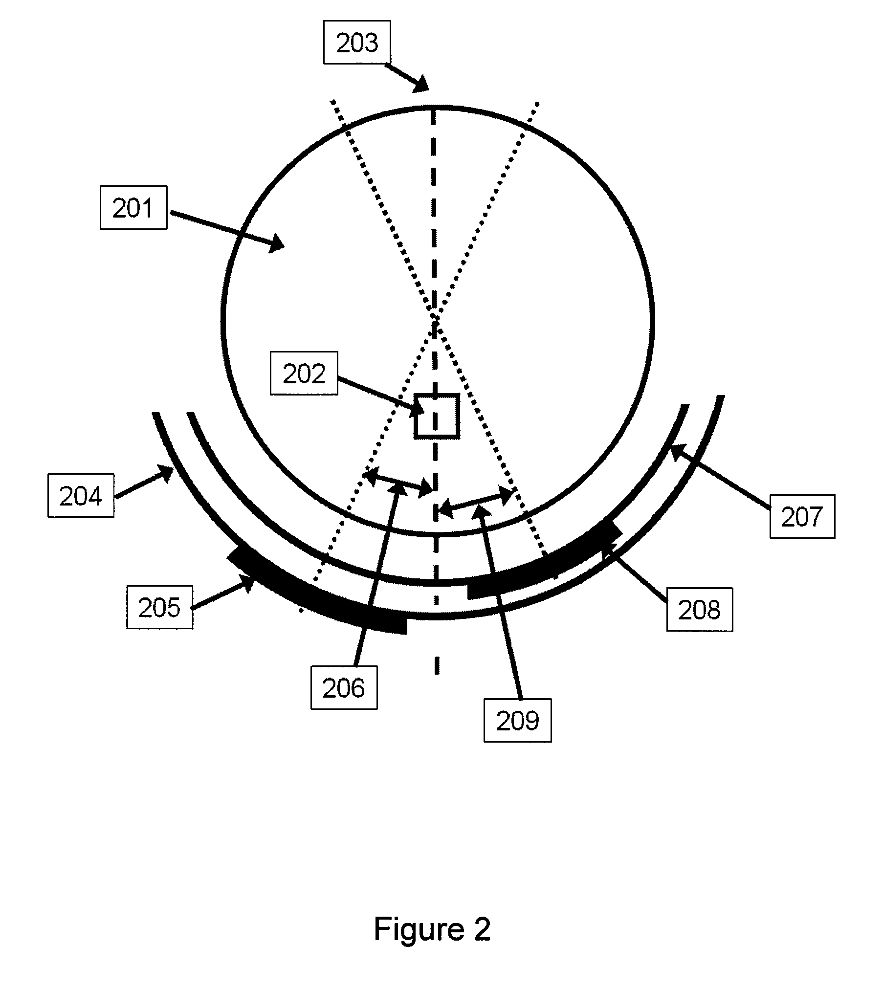
[0008]For example, exemplary embodiments of a coil arrangement according to the present disclosure can include, e.g., a plurality of elements which can be provided at an angle from one another. The angle can be selected to effectuate an imaging of a target region of interest at least one of a predetermined depth or range of depths, for example.

[0009]In certain exemplary embodiments according to the present disclosure, the angle can be selected to effectuate an exemplary predetermined transmit efficiency for at least one of the elements. Additionally, the exemplary angle can be selected to effectuate a predetermined receive sensitivity for at least one of the elements. Further, according to exemplary embodiments of the ...


PUM


Abstract

For example, the present disclosure provides exemplary embodiments of a coil arrangement that can include, e.g., a plurality of elements which can be provided at an angle from one another. The angle can be selected to effectuate an imaging of a target region of interest at least one of a predetermined depth or range of depths, for example. In certain exemplary embodiments according to the present disclosure, the angle can be selected to effectuate an exemplary predetermined transmit efficiency for at least one of the elements. Additionally, the exemplary angle can be selected to effectuate a predetermined receive sensitivity for at least one of the elements. Further, according to certain exemplary embodiments of a coil arrangement in according to the present disclosure, the angle can be adjusted manually and/or automatically.

Description

CROSS-REFERENCE TO RELATED APPLICATION(S)[0001]The present application relates to and claims priority from U.S. Patent Application No. 61 / 165,822 filed Apr. 1, 2009, the entire disclosure of which is hereby incorporated herein by reference.FIELD OF THE DISCLOSURE[0002]The present disclosure relates generally to exemplary embodiments of systems, apparatus and methods related to magnetic resonance imaging, and more particularly to a radio frequency (RF) coil arrangement for a high field magnetic resonance imaging (MRI) with optimized transmit and receive efficiency for a specified region of interest using, e.g., relative offset of transmit and receive elements, for example.BACKGROUND INFORMATION[0003]A significant challenge for magnetic resonance (MR) imaging at fields above 3 Tesla can be the relative lack of available radio frequency (RF) coils. In addition, the design of RF coils for high field can be complicated since, at the higher RF frequencies, there may be a more complex inte...

Claims


Application Information

Patent Timeline
IPC IPC(8): G01R33/44
CPCG01R33/34046G01R33/3453G01R33/3415G01R33/34053
Inventor WIGGINS, GRAHAM CHARLES
Owner NEW YORK UNIVERSITY
Why Eureka
Try Eureka