Method and system for miniature passive RFID tags and readers

a passive rfid and reader technology, applied in the field of contactless passive rfids, can solve the problems of too small range for reader and tag to operate effectively, too large dimensions of coils, sheets on which the coils are affixed, etc., and achieves the effects of reducing the physical size of rfid tags, facilitating handling, storage and application, and improving reliability and dependability of operation

Inactive Publication Date: 2010-10-07
ZAND AFSHIN
View PDF9 Cites 39 Cited by
  • Summary
  • Abstract
  • Description
  • Claims
  • Application Information

AI Technical Summary

Benefits of technology

[0024]The classification of RFID systems by the Auto-ID center, and its successor organization EPCglobal is stated below. The RFIDs in this invention are intended to perform almost all these.
[0025]RFIDs in this invention perform the functionality of all five classes, providing a superset of the foregoing, and constitute a new class of RFID.
[0026]Further objects and advantages of this invention are reduction in physical size of RFID Tags, thus enabling them to be placed on a great variety of items such as the typical item on a supermarket shelf; greater ease of handling, storage, and application; greater range; ability to operate without a direct path between Tag and Reader; improved reliability and dependability of operation; improved mechanical integrity; capability of localization of the Tag; low power of data transmission, in downlink or uplink, low complexity of hardware; low cost of manufacture.
[0027]A method and system for RFIDs whereby the Tag and Reader, the latter otherwise known as interrogator, scanner or energizer, communicate data by means independent from that used for transfer of energy from Reader to Tag. A narrowband carrier, or continuous wave (CW), with or without data, is used to energize the Tag, while a wideband, low-power signal, typically ultra wideband, is used for the exchange of data between Reader and Tag. The asymmetry established is leveraged to enable the Reader to emit energy to power the Tag at a much higher level than possible using the same band, or low power communications during subsequent data communication with the Tag. The disparity in power levels between these two, narrowband and wideband, is typically a thousand times, most often more. This scheme enables the Reader to efficiently energize the Tag using any available narrowband frequency, such as those on in the 5.15-5.85 GHz portion of the spectrum, or the 2.4-2.4835 GHz, or the 902-928 MHz (in Europe 869.4-869.65 MHz) where the Reader can output power in the range of Watts. Then Tag and Reader can communicate data in wideband, low-power mode, notably over a portion or over all of the ultra wideband spectrum 3.1-10.6 GHz, where the output power necessary is in the range of well under a milliwatt.
[0028]The combination of relatively high power to energize the Tag, and very low power to communicate data to and from the Tag, relieves the Tag from having to communicate by reflection to the Reader, and enables the establishment of a true radio link upstream from Tag to Reader (as well as of course downstream). This radio transmission uplink consists of a signal generated and transmitted by the Tag to the Reader, as opposed to reflections in use in prior art, and enables a greater degree of reliability of the communication link, avoids the double path loss, enables longer range communication between Tag and Reader, uses a smaller Antenna, and hence makes for a smaller Tag.

Problems solved by technology

The dimensions of the coil, hence the sheet on which the coil is affixed, are too large to enable item-level tracking.
With small Tags, the range is too low for Reader and Tag to operate effectively.

Method used


Image

  • Method and system for miniature passive RFID tags and readers
  • Method and system for miniature passive RFID tags and readers
  • Method and system for miniature passive RFID tags and readers

Examples


Embodiment Construction

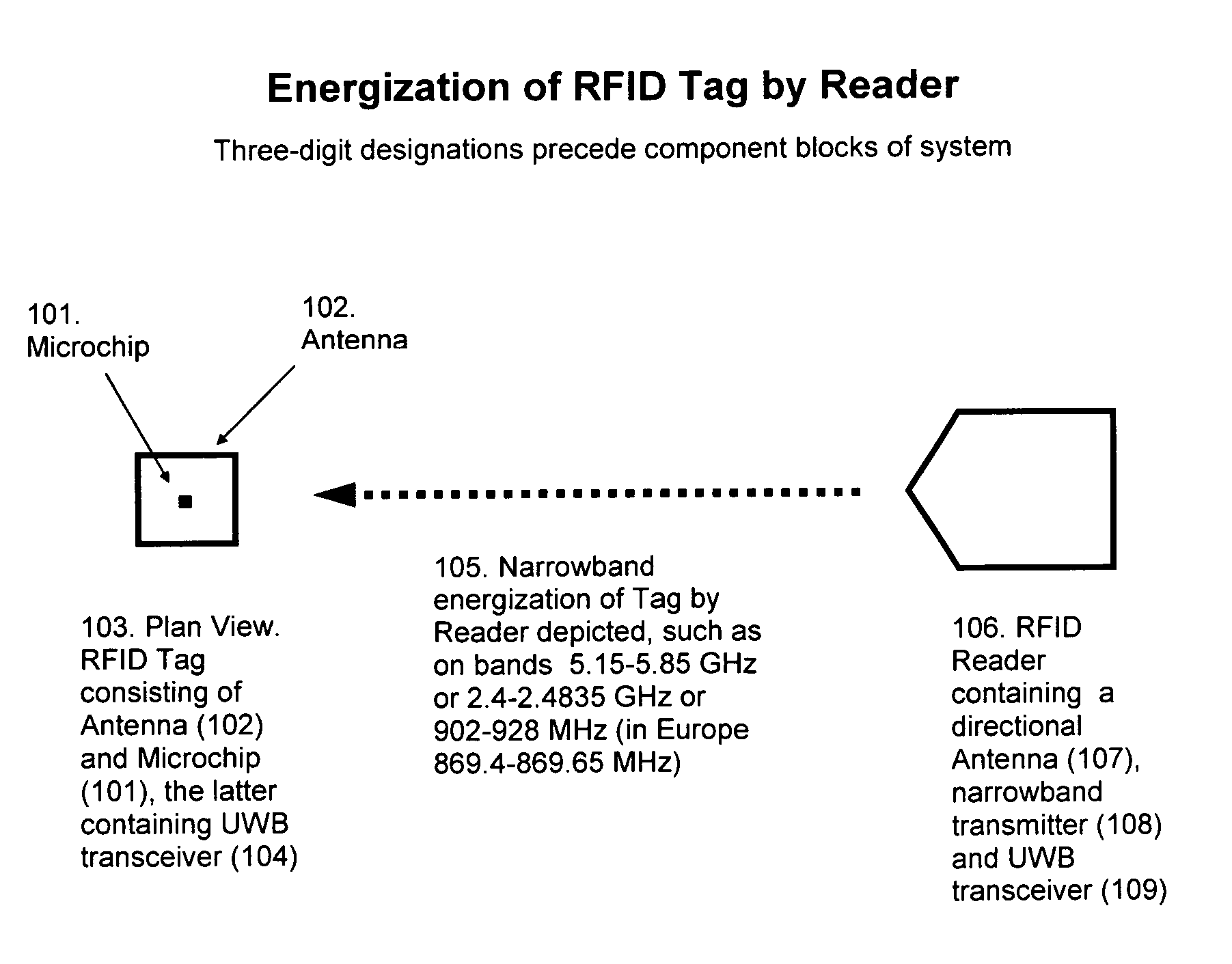
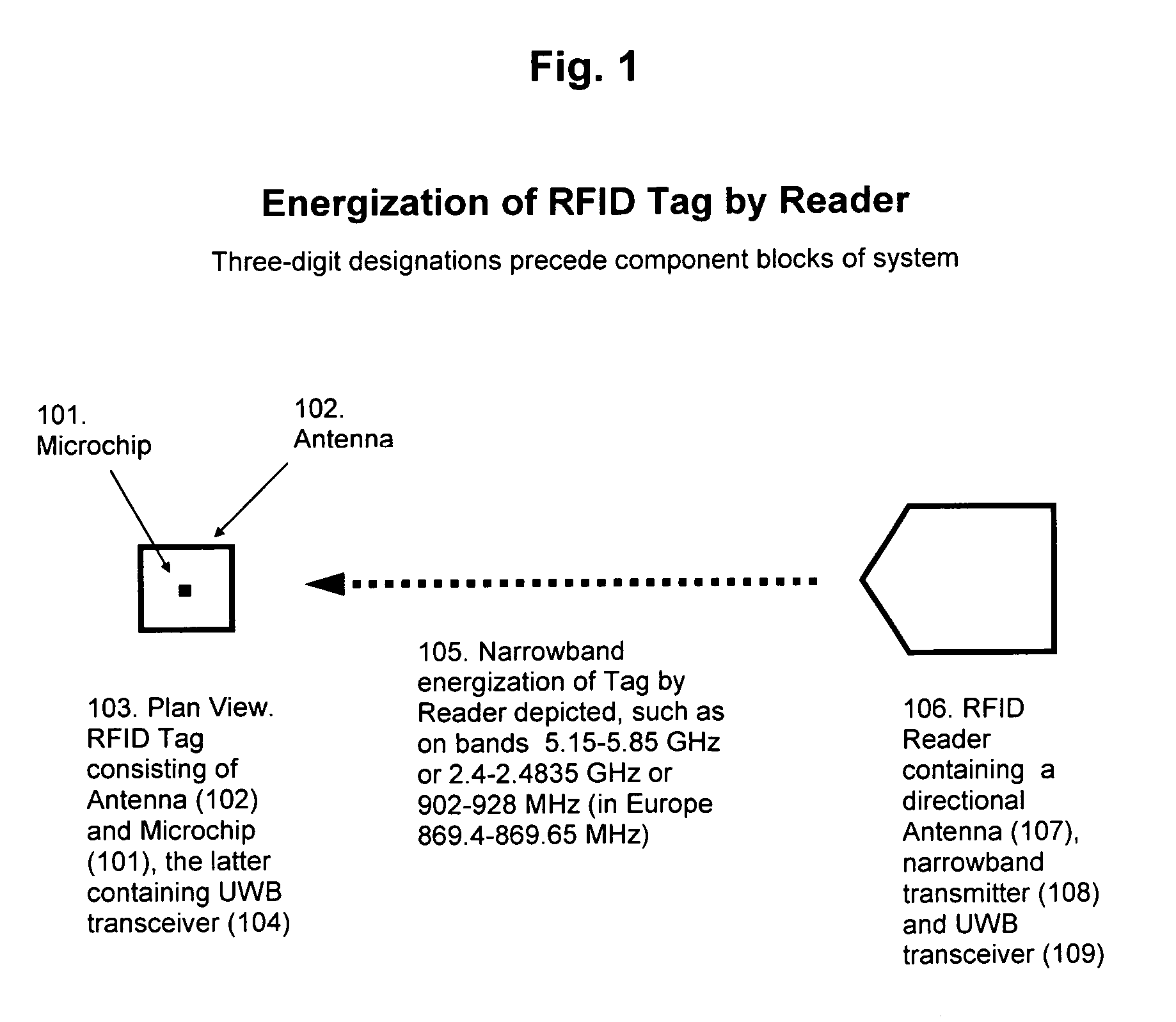
[0034]The Reader powers the Tag by transmission of a relatively high power narrowband carrier frequency, but communicates to / from the Tag by comparatively low power means over a wideband portion of the frequency spectrum. The energization of the Microchip on the Tag takes place by a different mechanism and uses a different method than is used for communication between Reader and Tag.

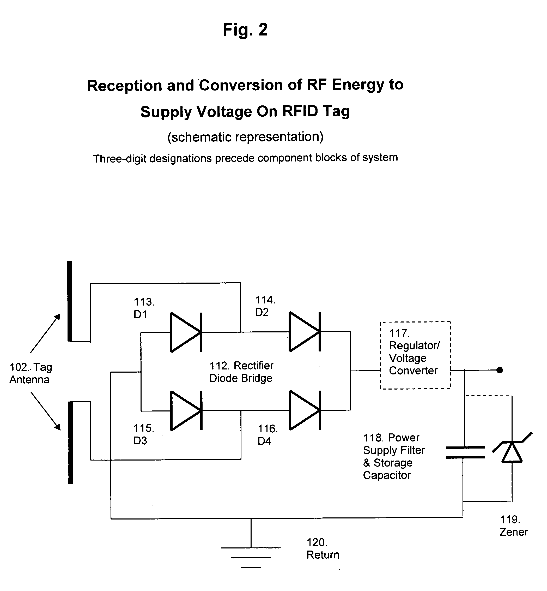
[0035]Reader and Tag communicate data by means of ultra wideband transmission and reception on a portion or all of the 3.1-10.6 GHz band. The total power for transmission by this means, in either direction, but in particular from Tag to is Reader, is well under a milliwatt. The Antenna for operation at this power is a small patch antenna. The size of the patch Antenna has already been demonstrated with antennas of approximately 19 mm by 25 mm in size, 17 mm by 20 mm in size, 8 mm by 10 mm in size, and 6 mm by 8 mm in size. The low power consumption of the Microchip means that the energy capture and stora...


PUM


Abstract

This invention makes possible small size, long range, reliable, low-power, low-cost RFIDs fulfilling the needs of the industry and the roadmap set for RFID, as by Walmart and the DoD. Tag energization and data communication take place by independent means. The invention employs low-power communication means, such as ultra wideband (UWB), for transfer of data between Tag and Reader, and relatively high power narrowband means to remotely energize the Tag. Said means of powering and communication mechanisms, further, are independent of the underlying process, or technology, of implementation of the Microchip on the Tag, as well as from the transceiver technology aboard the Reader. As such, they provide an ideal method and system by which to power and communicate with RFIDs, through cycles of evolution and changes in physical implementation technology.

Description

CROSS REFERENCES[0001]Priority is hereby claimed from Provisional Patent Application No. 60 / 582,988,[0002]Filing or 371 (c) Date: Jun. 25, 2004,[0003]Confirmation No. 2760.[0004]A copy of PPA is enclosed for reference.GOVERNMENT CONTRACT / FEDERAL R&D[0005]None. Not Applicable.FIELD OF THE INVENTION[0006]Field of the invention is that of contactless passive RFIDs. Contactless passive RFIDs are comprised of three basic components: the RFID Microchip, typically being an integrated circuit (IC), hereinafter referred to as “Microchip”, RFID antennas to which are attached these Microchips, hereinafter referred to as “Antenna”, and RFID readers, also known as interrogators, energizers or scanners, hereinafter referred to as “Reader” or “Reader subsystem”. The Microchip and Antenna, attached together, comprise an RFID tag, often also referred to as transponder, or inlay, hereinafter referred to as “Tag”. In the industry the Tag alone, for brevity of statement, is in usage often referred to a...

Claims


Application Information

Patent Timeline
Patent Type & Authority Applications(United States)
IPC IPC(8): H04Q5/22
CPCG01S5/14G06K7/10306G01S13/878G01S13/758
Inventor ZAND, AFSHIN
Owner ZAND AFSHIN
Why Eureka
Try Eureka