Method and apparatus for monitoring control channel in multiple carrier system

Inactive Publication Date: 2010-10-07
LG ELECTRONICS INC
View PDF12 Cites 196 Cited by
  • Summary
  • Abstract
  • Description
  • Claims
  • Application Information

AI Technical Summary

Benefits of technology

[0023]A burden due to blind decoding for monitoring a control channel can b

Problems solved by technology

Therefore, it may be ineffective if a channel structure of the sin

Method used


Image

  • Method and apparatus for monitoring control channel in multiple carrier system
  • Method and apparatus for monitoring control channel in multiple carrier system
  • Method and apparatus for monitoring control channel in multiple carrier system

Examples


Example

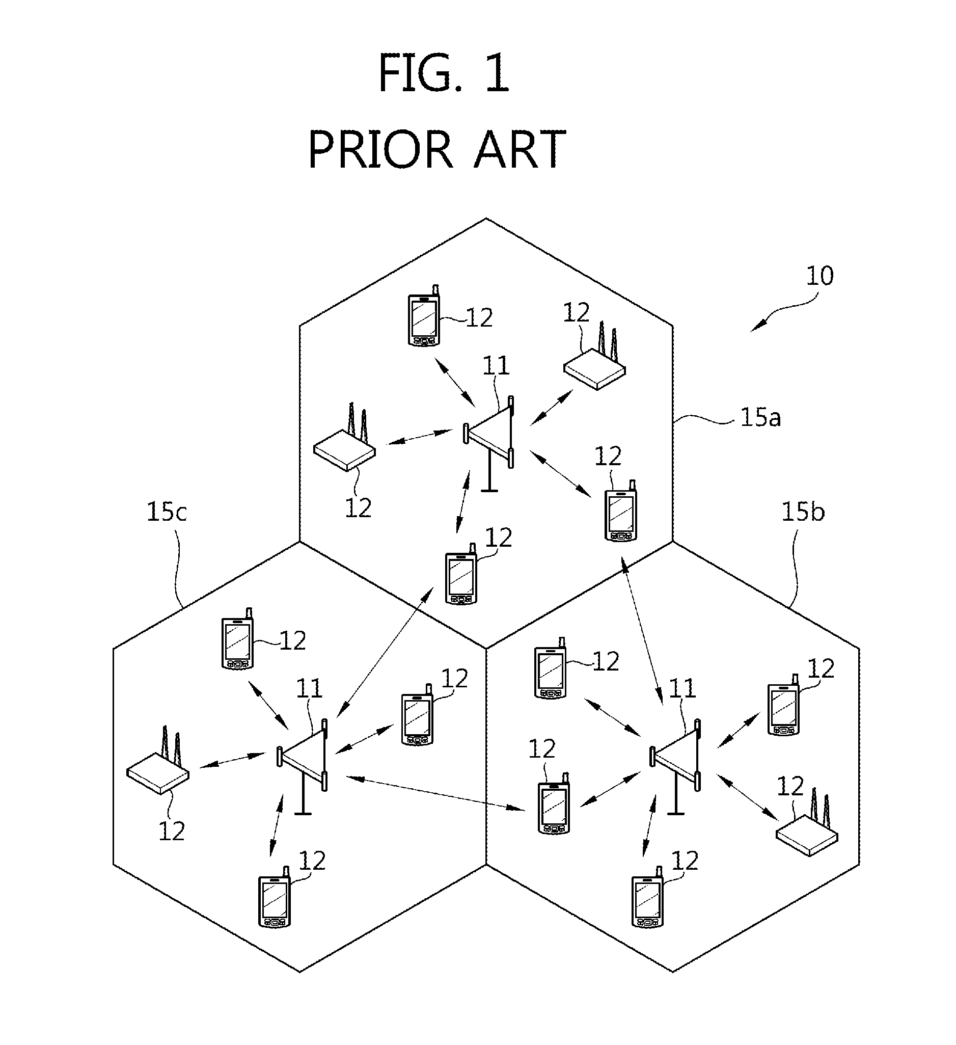
[0040]FIG. 1 shows a wireless communication system. A wireless communication system 10 includes at least one base station (BS) 11. Respective BSs 11 provide communication services to specific geographical regions (generally referred to as cells) 15a, 15b, and 15c. The cell can be divided into a plurality of regions (referred to as sectors).

[0041]A user equipment (UE) 12 may be fixed or mobile, and may be referred to as another terminology, such as a mobile station (MS), a mobile terminal (MT), a user terminal (UT), a subscriber station (SS), a wireless device, a personal digital assistant (PDA), a wireless modem, a handheld device, etc.

[0042]The BS 11 is generally a fixed station that communicates with the UE 12 and may be referred to as another terminology, such as an evolved node-B (eNB), a base transceiver system (BTS), an access point, etc.

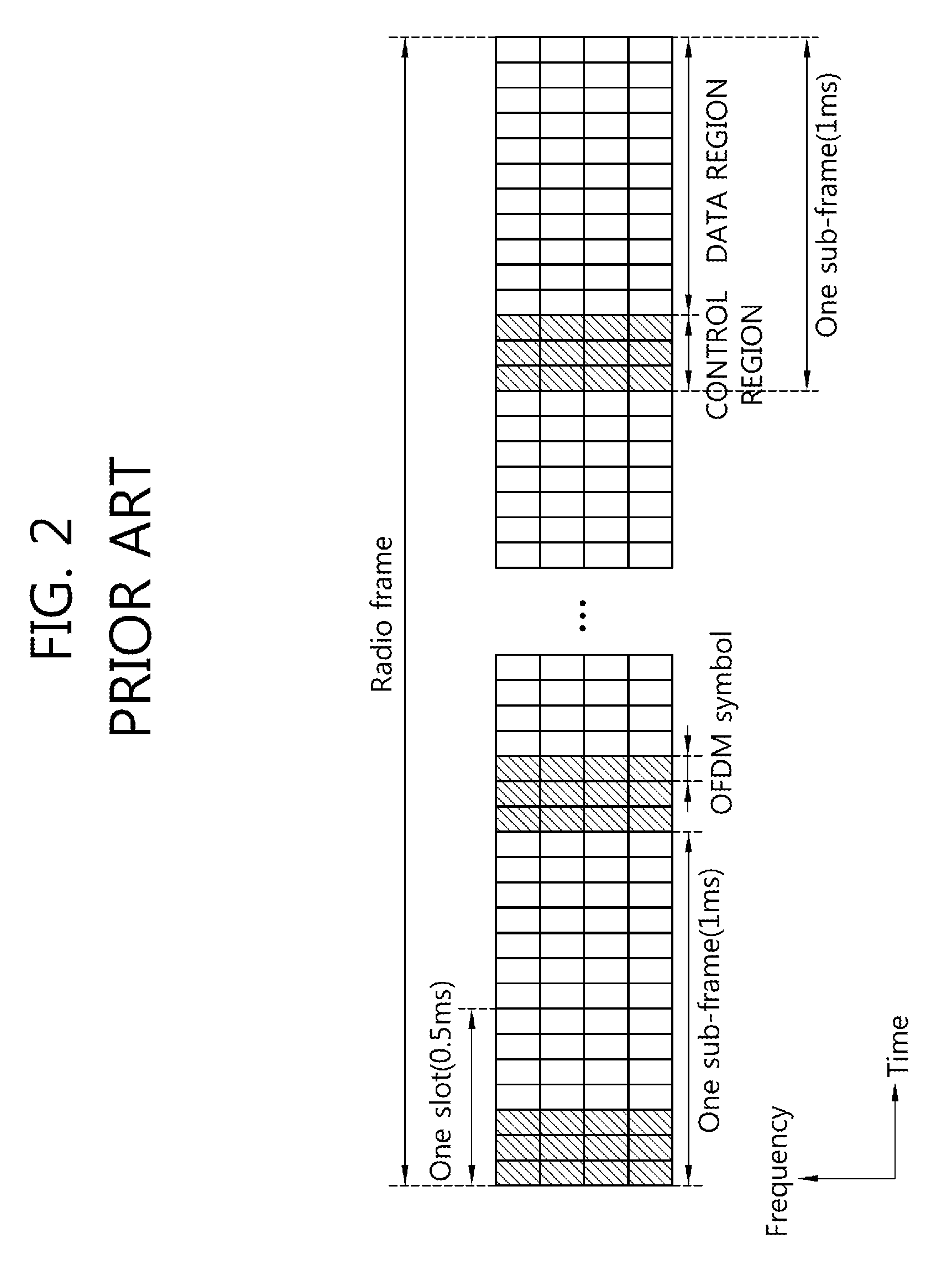
[0043]Hereinafter, downlink implies communication from the BS to the UE, and uplink implies communication from the UE to the BS. In the downl...


PUM


Abstract

A method and apparatus of monitoring a control channel in a multiple carrier system is provided. A user equipment monitors a plurality of candidate control channels within a control region of a subframe and receives reference control information on a reference control channel which is successfully decoded. The user equipment monitors the control region on a basis of the reference control information and receives link control information on a linked control channel which is successfully decoded. The link control information includes resource assignment information used to receive or transmit data packets via a plurality of component carriers.

Description

CROSS-REFERENCE TO RELATED APPLICATIONS[0001]This application claims the benefit of priority of U.S. Provisional application 61 / 165,913 filed on Apr. 2, 2009, U.S. Provisional application 61 / 167,855 filed on Apr. 8, 2009, and Korean Patent Application No. 10-2010-0029425 filed on Mar. 31, 2010, all of which are incorporated by reference in their entirety herein.BACKGROUND OF THE INVENTION[0002]1. Field of the Invention[0003]The present invention relates to wireless communications, and more particularly, to a method and apparatus for supporting multiple carrier in a wireless communication system.[0004]2. Related Art[0005]Wireless communication systems are widely spread all over the world to provide various types of communication services such as voice or data. In general, the wireless communication system is a multiple access system capable of supporting communication with multiple users by sharing available system resources (e.g., bandwidth, transmission power, etc.). Examples of th...

Claims


Application Information

Patent Timeline
IPC IPC(8): H04L12/26H04W4/00
CPCH04W36/385H04L5/0005H04L5/0007H04L5/001H04L5/0053H04L5/0055
Inventor KIM, SO YEONCHUNG, JAE HOONKWON, YEONG HYEONHAN, SEUNGHEE
Owner LG ELECTRONICS INC
Why Eureka
Try Eureka