Method and device for aligning components
a technology of component alignment and component, applied in the direction of conveyors, instruments, transportation and packaging, etc., can solve the problems of component being lost altogether, component being displaced from the center line of the pick-up nozzle, cumulative positioning error generation, etc., and achieves more freedom of movement and increased accuracy.
- Summary
- Abstract
- Description
- Claims
- Application Information
AI Technical Summary
Benefits of technology
Problems solved by technology
Method used
Image

Examples
first embodiment
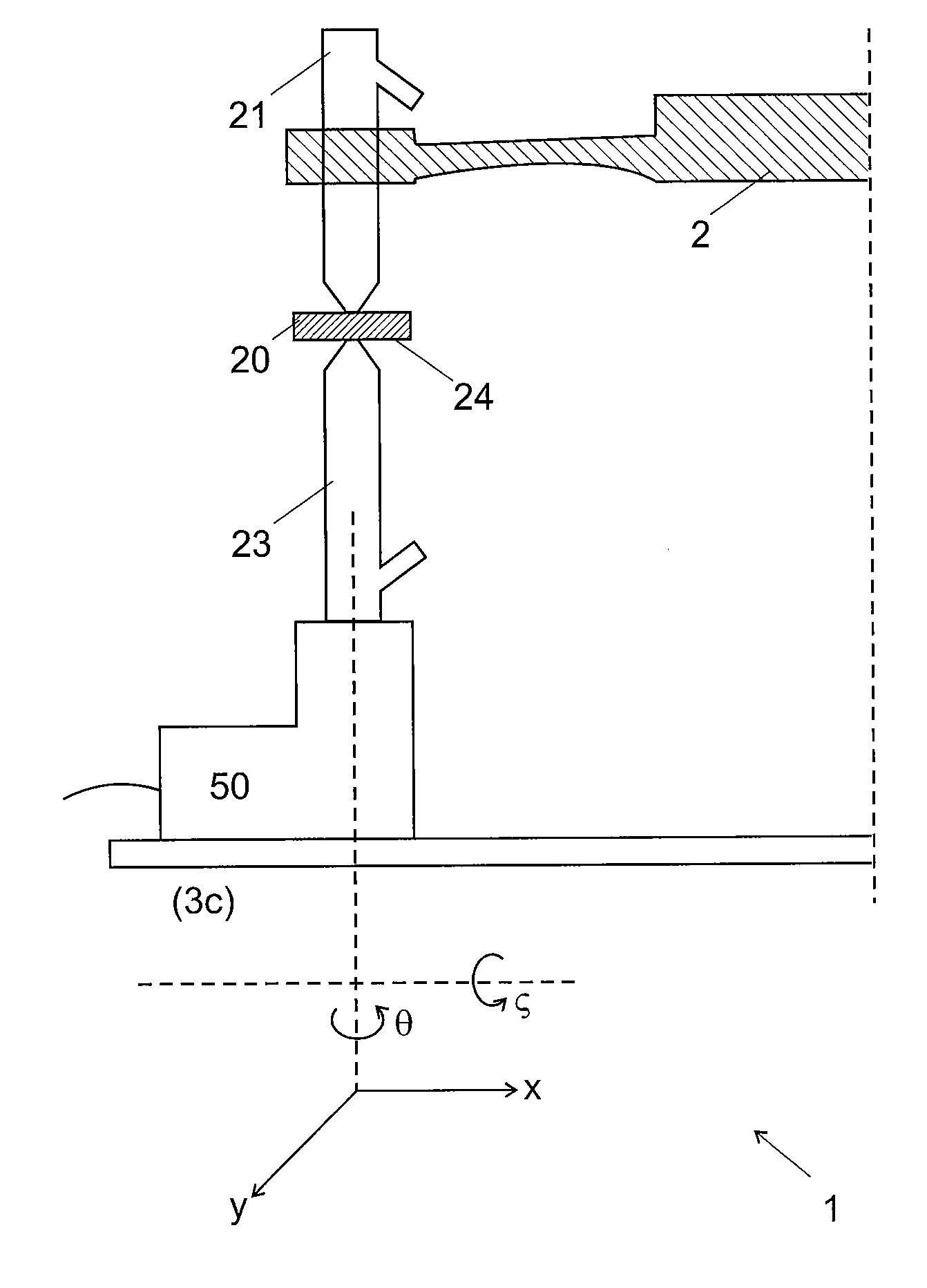
[0037]After determining the position correction, the pick-up nozzle 21 holding the component 20 is moved to the third process station 3c shown in FIG. 4 and comprising a task device. In a first embodiment, the task device is an aligning nozzle 23, connected to a source of negative and possibly positive pressure (not shown) and an actuator 50 enabling the aligning nozzle 23 to move in the in an x- and / or y-direction perpendicular to the plane of the aligning nozzle 23 and / or in the angular orientation θ relative to the aligning nozzle 23 rotation axis and / or along the angular orientation ζ relative to a plane perpendicular to the aligning nozzle 23. The aligning operation comprises the steps of:[0038]bringing the surface 24 of the component opposite to the one held by the pick-up nozzle 21 in contact with the aligning nozzle 23;[0039]holding the component20 on the aligning nozzle 23 by applying a negative pressure to the aligning nozzle 23 and subsequently releasing the component fro...
second embodiment
[0048]In a second embodiment shown in FIG. 5, the third process station 3c comprises an alignment device 25 that is not connected to a source of negative pressure for the alignment of the component 20. An actuator 50 enables the aligning device 25 to move in the in an x- and / or y-direction perpendicular to the plane of the aligning device 25 and / or in the angular orientation θ relative to the aligning device 25 rotation axis and / or along the angular orientation ζ relative to a plane perpendicular to the aligning device 25. The aligning operation comprises the steps of:[0049]bringing the surface 24 of the component opposite to the one held by the pick-up nozzle 21 in contact with the aligning device 25;[0050]releasing the negative pressure on the pick-up nozzle 21;[0051]moving the component with the aligning device 25 based on the position correction determined in the second process station 3b; [0052]holding the component 20 on the pick-up nozzle 21 by applying a negative pressure to...
third embodiment
[0057]In a third embodiment shown in FIG. 6, the task device of the third process station 3c is a test device 27 for performing a test or a series of tests on the component 20, for example, electrical tests. The test device 27 comprises a cavity 28 having dimensions mating with the shape and dimensions of the component 20. Electrical connectors are disposed on the surface of the cavity 28, two of these being illustrated in FIG. 6 by the numeral 29. Electrical connectors 29 are arranged to contact at least some of the electrical connectors (not shown) of the component 20. An actuator 50 enables the test device 27 to move in the in an x- and / or y-direction perpendicular to the plane of the test device 27, and / or in the angular orientation θ relative to the test device 27 rotation axis, and / or along the angular orientation ζ relative to a plane perpendicular to the test device 27. Here, the aligning operation comprises the steps of:[0058]align the test device 27 based on the position c...
PUM
 Abstract
Description
Claims
Application Information
 - R&D
- Intellectual Property
- Life Sciences
- Materials
- Tech Scout
- Unparalleled Data Quality
- Higher Quality Content
- 60% Fewer Hallucinations
Browse by: Latest US Patents, China's latest patents, Technical Efficacy Thesaurus, Application Domain, Technology Topic, Popular Technical Reports.
© 2025 PatSnap. All rights reserved.Legal|Privacy policy|Modern Slavery Act Transparency Statement|Sitemap|About US| Contact US: help@patsnap.com