

Fuel cell system operation method
- Summary
- Abstract
- Description
- Claims
- Application Information
AI Technical Summary
Benefits of technology
Problems solved by technology
Method used
Image

Examples
first embodiment
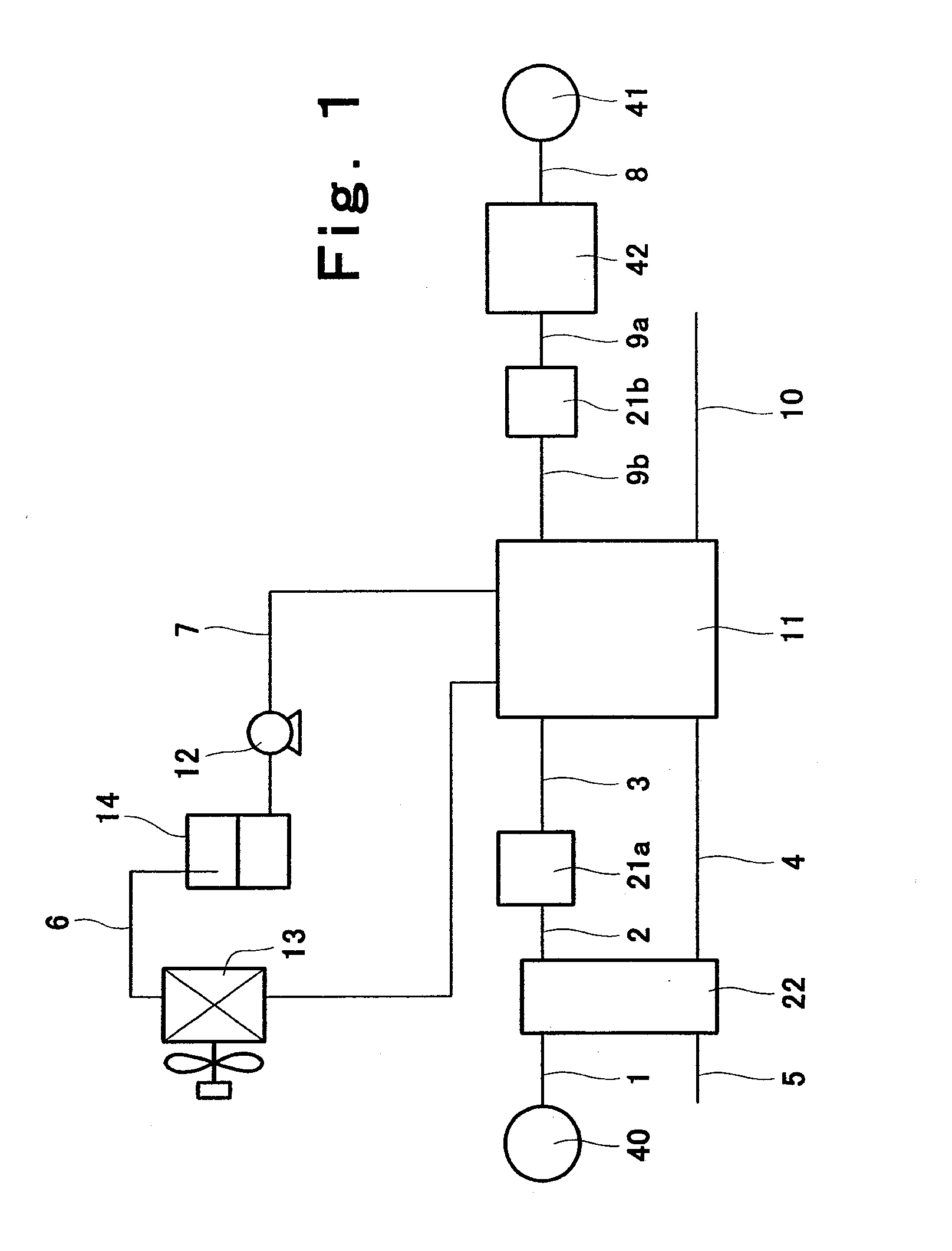
[0049]FIG. 1 diagrammatically shows a structure of a fuel cell cogeneration system (hereinafter simply referred to as “fuel cell system”) according to a first embodiment of the invention.
[0050]As shown in FIG. 1, the fuel cell system of the present embodiment includes, as main components, an air supply unit 40, a pre-humidifying unit 22, a humidifying unit 21a, a fuel cell 11, a fuel supply unit 41, a fuel processing unit 42, a humidifying unit 21b, a cooling water heat radiator 13, a cooling water tank 14, and a cooling water pump 12.
[0051]Air supplied from the air supply unit 40 to the pre-humidifying unit 22 through an air path 1 is humidified by the pre-humidifying unit 22 as described later. The humidified air is supplied to the humidifying unit 21a through an air path 2 and further humidified by the humidifying unit 21a. As the humidifying unit 21a, conventional humidifiers may be used, examples of which include a bubbler for performing humidification by letting air pass throu...
second embodiment
[0062]FIG. 4 diagrammatically illustrates a structure of a fuel cell system according to a second embodiment of the invention. As shown in FIG. 4, the fuel cell system of the present embodiment has the same structure as in the fuel cell system of the first embodiment, except that a humidifying unit 21a′ for humidifying the supply air with circulating cooling water used for cooling the fuel cell 11 is provided in place of the humidifying unit 21a constituted by a conventional humidifier such as bubblers. Hereinafter, the point of difference will be described.
[0063]In the system of the present embodiment, the air path 2 for supplying the air processed by the pre-humidifying unit 22 is connected to the humidifying unit 21a′ and the air path 3 for supplying the air humidified by the unit 21a′ to the fuel cell 11 is also connected to the humidifying unit 21a′. Connected further to the humidifying unit 21a′ are cooling water paths 6a, 6b through which the cooling water recovered from the ...
third embodiment
[0068]FIG. 5 diagrammatically shows a structure of a fuel cell system according to a third embodiment of the invention. As shown in FIG. 5, the structure of the fuel cell system of the third embodiment is similar to that of the second embodiment, except that heat dissipated from the cooling water by a cooling water heat radiator 13, which comprises a heat exchanger, is utilized for heating the water stored in a hot water reserve tank 45. The point of difference will be described below.
[0069]The system of the present embodiment has the hot water reserve tank 45, a hot water pump 44 for pumping water stored in the tank 45, a hot water circulation path 15 for bringing the water sent from the tank 45 back to the tank 45 by way of the cooling water heat radiator 13. In such a system, heat is shifted from the cooling water after utilized for the humidification in the humidifying unit 21a′ to the cooling water heat radiator 13 and this heat is given to the water circulating in the hot wate...
PUM
 Abstract
Description
Claims
Application Information