
Spot welding equipment for machining metallic material and with monitoring function

A technology of metal materials and functional points, applied in the direction of metal processing equipment, welding equipment, arc welding equipment, etc., can solve the problems of reducing work efficiency, staff interference, and affecting the working environment of the workshop, so as to shorten the time and speed of intermediate pauses The control is stable and reliable, and the alarm prompt effect is remarkable

Inactive Publication Date: 2017-11-21
SUZHOU CONYET AUTOMATION TECH
View PDF6 Cites 1 Cited by
  • Summary
  • Abstract
  • Description
  • Claims
  • Application Information

AI Technical Summary

Problems solved by technology

[0004] 1. There is no automatic spot welding equipment that can be specially used for processing metal materials. When using general automatic spot welding equipment, the workpiece needs to be clamped and fixed manually, and large arc light and smoke will also be generated during welding operations. , so that the staff need to stop and rest halfway, which reduces the work efficiency and affects the working environment of the workshop;
[0005] 2. The precision of spot welding is low, and at the same time, the noise during spot welding processing is relatively large, which is easy to cause interference to the staff;
[0006] 3. The safety is poor. The staff cannot monitor the specific working status of the spot welding manipulator and the clamping mechanism in real time. Therefore, deviations are prone to occur during spot welding work, and they cannot respond in time when failures or accidents occur, and the equipment cannot be guaranteed to be efficient and stable for a long time to run

Method used


Image

  • Spot welding equipment for machining metallic material and with monitoring function

Examples


Embodiment 1

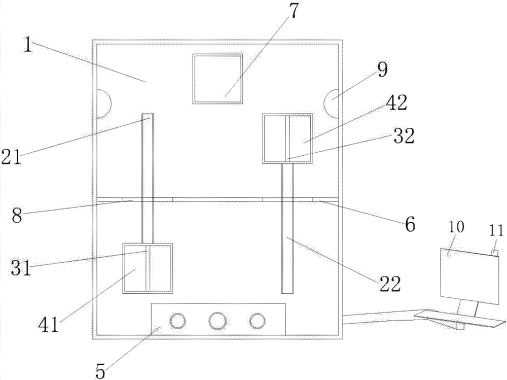
[0024] Such as figure 1 As shown, a spot welding equipment with monitoring function for processing metal materials in this embodiment includes a fuselage 1, a first guide rail 21, a second guide rail 22, a first slide bar 31, a second slide bar 32, The first automatic clamping mechanism 41, the second automatic clamping mechanism 42, the electrical control panel 5, the closing mechanism 6, the spot welding manipulator 7, the through hole 8, the CCD camera 9, the display 10 and the automatic alarm device 11.

[0025] The connection relationship of the above-mentioned components is as follows: the left and right sides of the middle part of the fuselage 1 are respectively provided with a first guide rail 21 and a second guide rail 22, and the first automatic clamping mechanism 41 is provided with the first slide bar 31 at the bottom. Slide back and forth on the first guide rail 21, and the second automatic clamping mechanism 42 slides back and forth on the second guide rail 22 th...


PUM


Abstract

The invention discloses spot welding equipment for machining a metallic material and with a monitoring function, and relates to the technical field of automatic equipment. A first automatic clamping mechanism slides back and forth on a first guide rail through a first sliding rod arranged at the bottom. A second automatic clamping mechanism slides back and forth on a second guide rail through a second sliding rod arranged at the bottom. A sealing mechanism is arranged in the center of a machine body, and the left side and the right side of the sealing mechanism are provided with through holes. An electric control panel and a spot welding manipulator are arranged at the two ends of the machine body correspondingly. The machine body is connected with a displayer through a telescopic rod. An automatic warning device is arranged at the top of the displayer. CCD cameras connected with the displayer are arranged on the surfaces of the parts, on the two sides of the spot welding manipulator, of the machine body. Through the spot welding equipment, the spot welding efficiency and quality of metallic workpieces are greatly improved, harm of arc light and smoke to operators is reduced, the equipment is safe and environmentally friendly, operators can operate the equipment easily, working noise is low, and long-time efficient and stable spot welding operation is ensured.

Description

technical field [0001] The invention relates to the technical field of automation equipment, in particular to spot welding equipment with a monitoring function for processing metal materials. Background technique [0002] Automatic spot welding equipment is an automatic welding machine based on motor control technology, single-chip microcomputer control technology, PLC control technology and numerical control technology. It is mainly composed of automatic workpiece loading and unloading mechanisms and welding automation systems; Nowadays, automatic spot welding machines have been widely used in plastics, automobile manufacturing, metal processing, hardware appliances, steel structures, pressure vessels, machining and manufacturing, shipbuilding, aerospace and other fields, which greatly improve the appearance and internal quality of welded parts, and The stability of quality is guaranteed and the labor intensity is reduced. In recent years, with the continuous development...

Claims


Application Information

Patent Timeline
IPC IPC(8): B23K9/007B23K9/12B23K9/32
CPCB23K9/32B23K9/007B23K9/12B23K9/321
Inventor 陈胜虎
Owner SUZHOU CONYET AUTOMATION TECH
Learn More