Efficient heat preservation dead head production device

A technology for production equipment and thermal insulation risers, which is applied to casting molding equipment, metal processing equipment, casting molds, etc., can solve the problems of easy deformation of risers, low production efficiency, and inability to achieve continuity, etc. Simple, good separation effect

Active Publication Date: 2017-06-27
长兴鼎峰铸材科技股份有限公司
View PDF7 Cites 2 Cited by
  • Summary
  • Abstract
  • Description
  • Claims
  • Application Information

AI Technical Summary

Problems solved by technology

[0005] The purpose of the present invention is to address the deficiencies of the prior art. By setting the conveying part, the discharging part and the lifting and rotating mechanism in the forming part, it overcomes the low production efficiency and the inability to achieve continuity in the production riser process of the prior art. And the problem that the riser is easy to deform

Method used


Image

  • Efficient heat preservation dead head production device
  • Efficient heat preservation dead head production device
  • Efficient heat preservation dead head production device

Examples


Embodiment 1

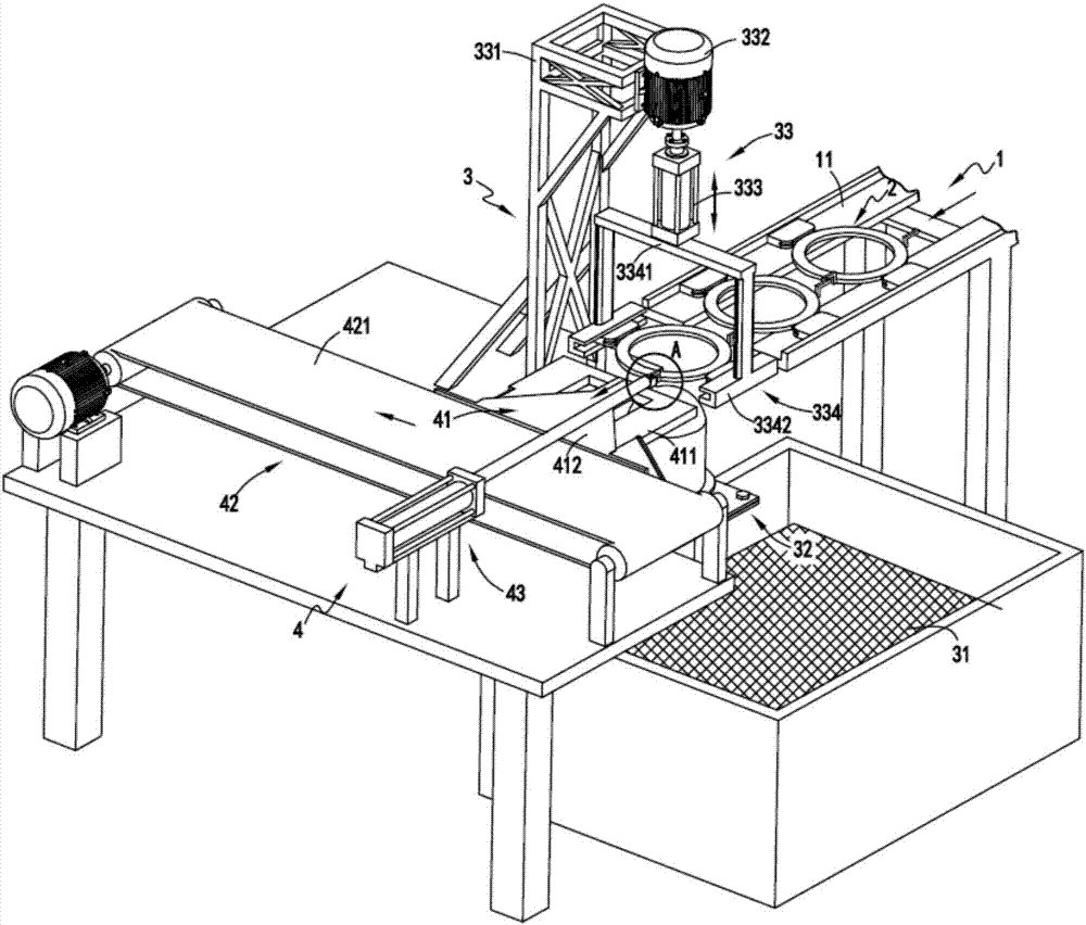
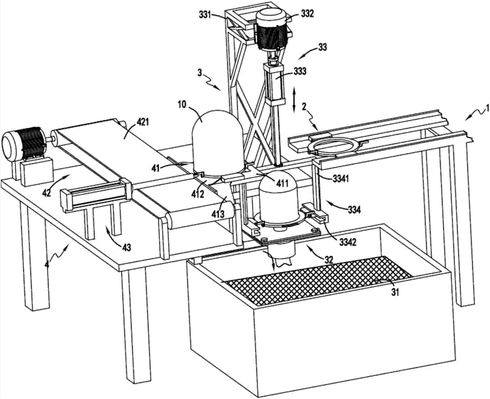
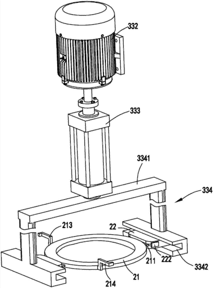
[0040] figure 1 Schematic diagram of the structure when the pallet assembly of the insulation riser is efficiently produced on the support device, figure 2 Schematic diagram of the structure when the forming device for the high-efficiency production equipment of the thermal insulation riser connects the supporting parts and starts to transfer into the mud pool, image 3 It is a schematic diagram of the structure of the lifting and rotating mechanism, Figure 4 It is a schematic diagram of the structure when the supporting device drives the tray assembly to the forming device, Figure 5 It is a schematic diagram of the structure when the supporting part is separated from the supporting part and the forming device drives the supporting part to turn over, Figure 6 is a schematic diagram of the structure of the component separation mechanism, Figure 7 is a schematic diagram of the structure of the pallet assembly, Figure 8 It is a schematic diagram of the front view when t...

Embodiment 2

[0051] Such as figure 1 , figure 2 , image 3 , Figure 4 , Figure 5 , Figure 6 , Figure 7 , Figure 8 , Figure 9 and Figure 10 As shown, the components that are the same as or corresponding to those in the first embodiment are marked with the corresponding reference numerals in the first embodiment. For the sake of simplicity, only the differences from the first embodiment will be described below. The difference between the second embodiment and the first embodiment is that the pulling mechanism 43 includes a telescopic device 431 and a hook block 4312 fixed at the end of the telescopic rod 4311 of the telescopic device 431; The front end is provided with a hook block a213 that cooperates with the hook groove 4313 opened by the hook block 4312, and the rear end of the support member 21 is provided with a hook block that cooperates with the hook block a213 of the next support member 21. b214.

[0052] Further, the bent portion 4314 of the hooking block 4312 fac...


PUM


Abstract

The invention relates to an efficient heat preservation dead head production device. The efficient heat preservation dead head production device comprises a conveying part used for conveying a tray assembly, a forming part and a discharging part. The tray assembly comprises a material supporting piece and a supporting piece. The forming part comprises a mud pit, a forming mechanism and a lifting rotating mechanism. The lifting rotating mechanism is used for driving the tray assembly conveyed by the conveying part to the forming mechanism. After the forming mechanism finishes dead head forming, the tray assembly and a formed dead head are driven to be separated from the forming mechanism and return to the initial position. The discharging part is arranged at the rear end of the forming part. The discharging part comprises an assembly separating mechanism, an output mechanism arranged at the rear end of the assembly separating mechanism, and a pulling mechanism, wherein the pulling mechanism is used for pulling the tray assembly on the lifting rotating mechanism and the formed dead head to move to the output mechanism from the lifting rotating mechanism via the assembly separating mechanism. The problems that in the prior art, the production efficiency in the dead head production process is low, continuity cannot be achieved, and the dead head is prone to deformation are solved.

Description

technical field [0001] The invention relates to the technical field of riser production equipment, in particular to high-efficiency production equipment for thermal insulation risers. Background technique [0002] The riser made of low thermal conductivity material is called thermal insulation riser. Compared with ordinary riser, the metal liquid in the riser has a longer solidification time and better feeding effect. There are many shapes and structures of thermal insulation risers. At present, the principle of adsorption molding is generally used in the manufacture of thermal insulation risers. In the pulp pool turned over by the adsorption molding equipment, the slurry pump vacuumizes the inside of the mold, and the slurry is attached to the surface of the mold to form a thermal insulation riser. Mouth, the existing thermal insulation riser production equipment generally has a low degree of automation and low production efficiency, and in order to realize automation, it i...

Claims


Application Information

Patent Timeline
Patent Type & Authority Applications(China)
IPC IPC(8): B22C9/08
CPCB22C9/088
Inventor 樊新峰
Owner 长兴鼎峰铸材科技股份有限公司
Why Eureka
Try Eureka