Fuel cell system

a fuel cell and system technology, applied in the field of fuel cell technology, can solve the problems of affecting the convenience of users, and affecting the smooth supply of fuel, so as to improve the convenience of users and eliminate the state

Active Publication Date: 2010-10-07
TOYOTA JIDOSHA KK
View PDF0 Cites 3 Cited by
  • Summary
  • Abstract
  • Description
  • Claims
  • Application Information

AI Technical Summary

Benefits of technology

[0006]There would thus be a requirement for improving the user's convenience at the checkup time of a fuel cell system having an operation mode for eliminating the state of flooding.

Problems solved by technology

In this case, the generated water remaining in the fuel cells may be frozen to interrupt the smooth supply of fuel.
This may lead to failure of power generation.
The generated water that is not frozen but is accumulated in the vicinity of electrolyte membranes, this phenomenon is generally called ‘flooding’, may still interrupt the smooth supply of fuel and lower the performance of the fuel cells.
Any of such flooding elimination processes requires the additional power consumption and thereby worsens the fuel consumption rate.

Method used


Image

  • Fuel cell system
  • Fuel cell system
  • Fuel cell system

Examples


first embodiment

A. First Embodiment

B. Second Embodiment

C. Other Aspects

A1. Configuration of Fuel Cell Vehicle

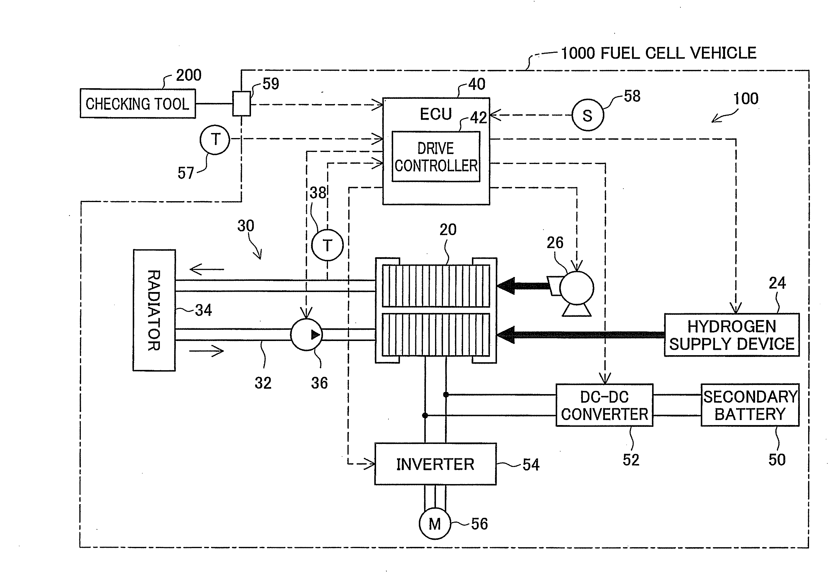
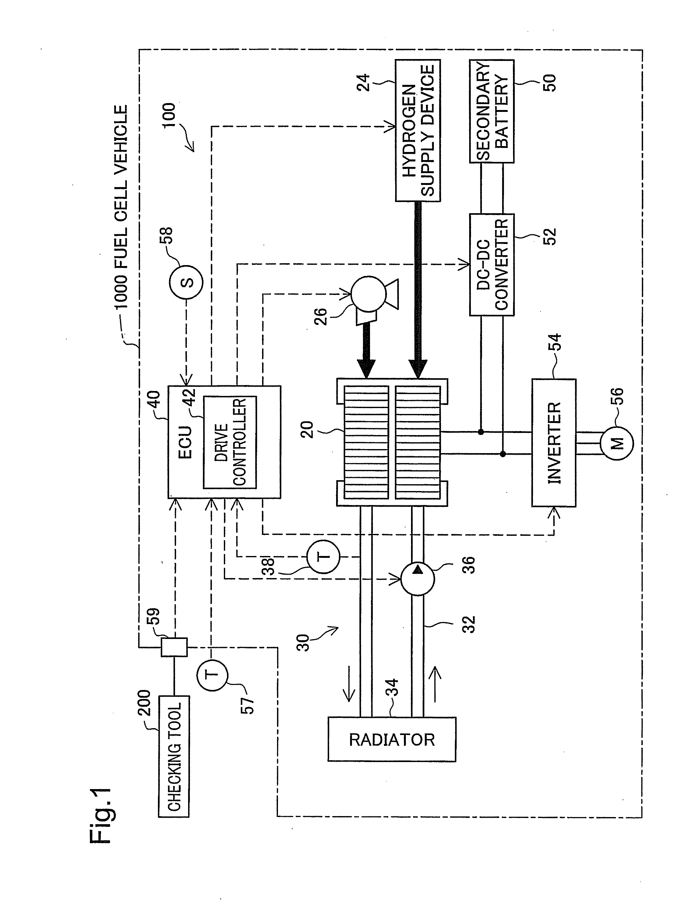
[0027]FIG. 1 is an explanatory view schematically illustrating the configuration of a fuel cell vehicle 1000 equipped with a fuel cell system 100 in a first embodiment of the invention. The fuel cell vehicle 1000 includes the fuel cell system 100, a secondary battery 50, a motor 56, an ECU 40, a DC / DC converter 52, and an inverter 54 as main components. The fuel cell vehicle 1000 is driven with driving power of the motor 56, which is activated by a fuel cell stack 20 as a main power source and the secondary battery 50 as an auxiliary power source.

[0028]The ECU 40 is constructed as a microcomputer-based logic circuit and controls the operations of the respective constituents in the fuel cell vehicle 1000. The ECU 40 receives signals from various sensors and switches provided on the fuel cell vehicle 1000, while outputting control signals to the DC / DC converter 52 and the inverter 54 to contro...

second embodiment

B. Second Embodiment

[0062]A fuel cell system of a second embodiment is mounted on the fuel cell vehicle 1000 in the same manner as the first embodiment. The fuel cell system of the second embodiment has the same configuration as that of the first embodiment, except a different flooding elimination control routine performed by the ECU 40. The like constituents to those of the first embodiment are thus expressed by the like numerals and symbols and are not specifically described here.

B1. Operations of Embodiment

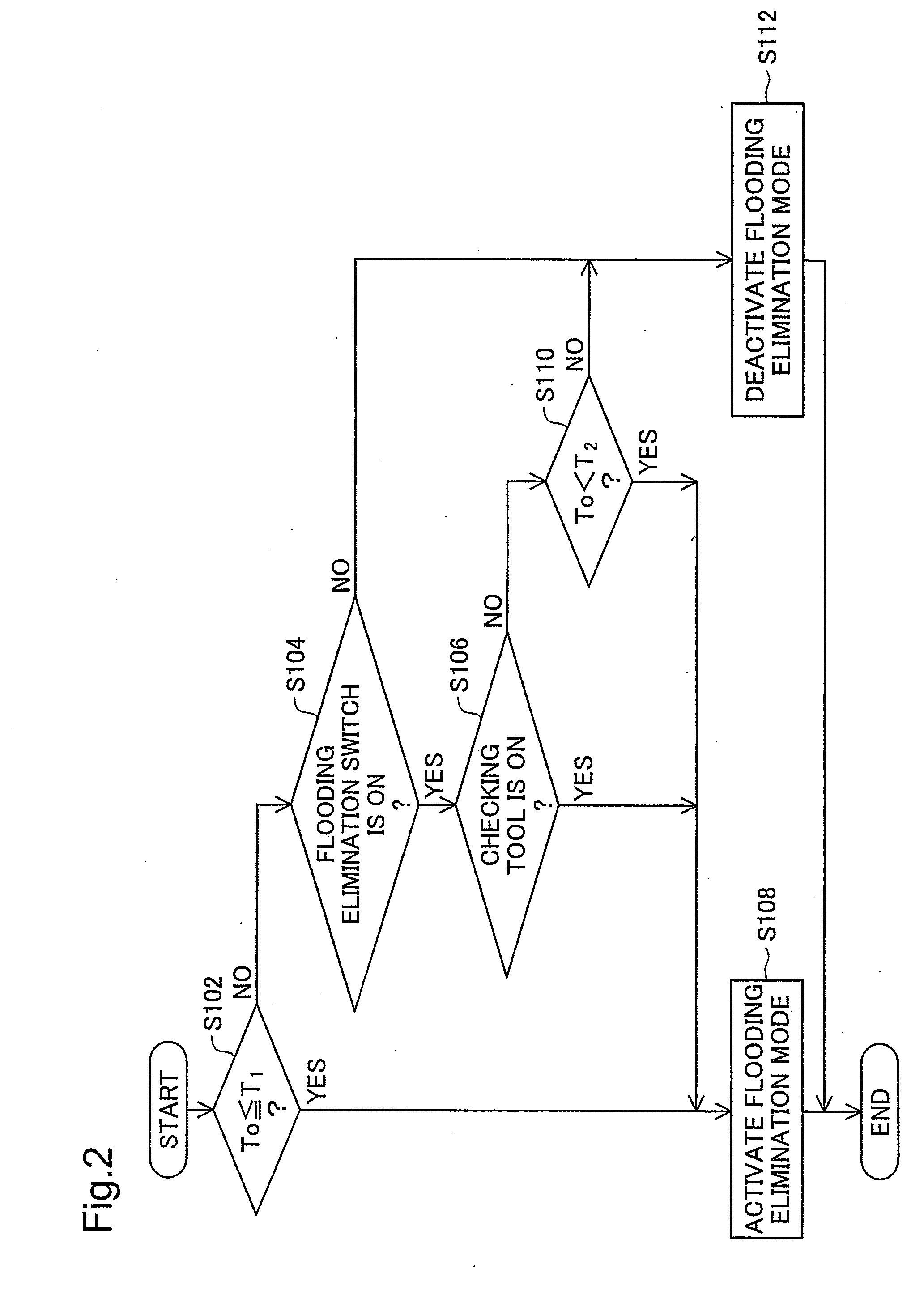
[0063]FIG. 5 is a flowchart showing a flooding elimination control routine performed in the second embodiment. In the second embodiment, as in the first embodiment, at the checkup time of the fuel cell stack 20, the checker connects the checking tool 200 to the input / output terminals 59 via a connection cable, powers the checking tool 200 ON, and starts the fuel cell system 100. In response to reception of a power-on signal from the checking tool 200, the ECU 40 identifies inpu...


PUM

PropertyMeasurementUnit
temperatureaaaaaaaaaa
water contentaaaaaaaaaa
heat retentionaaaaaaaaaa

Abstract

A fuel cell system has a flooding elimination mode as one of available operation modes of fuel cells and includes a drive controller. When the ambient temperature of the fuel cell system is not higher than a preset first temperature, the drive controller causes the fuel cells to be driven in the flooding elimination mode. When the ambient temperature of the fuel cell system is not lower than a preset second temperature that is higher than the first temperature, the drive controller prohibits the fuel cells from being driven in the flooding elimination mode. On the occasion of input of a checkup instruction of the fuel cells, the drive controller causes the fuel cells to be driven in the flooding elimination mode, independently of the ambient temperature. This arrangement effectively improves the user's convenience at the checkup time of the fuel cell system having the operation mode for eliminating the state of flooding.

Description

TECHNICAL FIELD[0001]The present invention relates to a fuel cell technology.BACKGROUND ART[0002]During power generation, water is generated in fuel cells through electrochemical reaction of hydrogen with oxygen, hereafter the water thus generated may be referred to as ‘generated water’. For example, in a vehicle equipped with fuel cells, the fuel cells may be expected to start in a subfreezing environment. In this case, the generated water remaining in the fuel cells may be frozen to interrupt the smooth supply of fuel. This may lead to failure of power generation.[0003]In a fuel cell system including fuel cells, one proposed technique drives the fuel cells in a heat retention mode in response to the user's selection in order to prevent the generated water from being frozen and stops the operation of the fuel cells in the heat retention mode when the ambient temperature reaches a sufficiently high level (see, for example, Japanese Patent Laid-Open No. 2005-108832, No. 2005-317211, ...

Claims


Application Information

Patent Timeline
Patent Type & Authority Applications(United States)
IPC IPC(8): H01M8/04
CPCH01M8/04007H01M8/04291H01M8/0432H01M8/04358H01M8/04723Y02T90/32H01M8/04753H01M8/04768H01M8/04947H01M2250/20Y02E60/50H01M8/04731Y02T90/40
Inventor KAJIWARA, SHIGETOASO, SHINJI
Owner TOYOTA JIDOSHA KK
Why Eureka
Try Eureka