
Dental retraction material having enhanced fluid absorption

a technology of retraction material and fluid absorption, which is applied in the field of retraction material, can solve the problems of inability to make an accurate impression of the prepared tooth, inability to apply additional bleeding into the space, and time-consuming and painful or extremely uncomfortable for patients, etc., and achieves the effect of reducing the amount of fluid in the space between the gum and the base of the tooth, easy application and convenient benting

Active Publication Date: 2010-10-07
CENTRIX
View PDF46 Cites 14 Cited by
  • Summary
  • Abstract
  • Description
  • Claims
  • Application Information

AI Technical Summary

Benefits of technology

[0018]It is an advantage of the present invention that retraction and drying of the sulcus is accomplished in a single step.
[0019]It is another advantage of the present invention that the retraction martial is easily applied.
[0020]It is a feature of the present invention that an astringent and an absorbing agent are provided in a single retraction material.
[0021]It is another feature of the present invention that it is applied precisely with a syringe.
[0022]It is yet another feature of the present invention that the retraction material may be applied with cannulae that may be easily bent.
[0023]It is still another feature of the present invention that the retraction material may be dispensed with a plastic capsule or tip having a nozzle.

Problems solved by technology

Upon the removal of the cord, frequently coagulum forms to stop the bleeding or seepage of fluid and is removed with the cord which may result in the seepage of additional bleeding into the space.
As a result, an impression cannot be made of the prepared tooth until the additional bleeding can be controlled or stopped.
Thus, the traditional procedure for enlarging the space between the gum and the base of the tooth necessary for taking an accurate impression is tedious, time consuming and painful or extremely uncomfortable for the patient.
Also, there exists the danger that the dentist may accidentally force the cord beyond the physiologic limit of the space to create a potential periodontal pocket which can cause the tooth to be eventually lost.
The general practice of using the cord technique is relatively difficult and tedious for the dentist.
In the event that the space between the tooth and the gum that has to be retracted is very small, it becomes even more difficult for the dentist to place the cord without injuring the gum tissue and from forcing the cord beyond the physiologic limit, and renders the procedure more painful for the patient.
Further, the placing of the cord is not a procedure which the dentist may delegate to a dental assistant or dental hygienist.
Also, the packing of a retraction cord is a most disliked step to perform during a crown or bridge restoration procedure.
The large gauge opening of the cannula renders the bending of the cannula difficult and which bending is often required in order to place the material in difficult to reach places within a patient's mouth.
Because the opening of the cannula is quite large, difficulty is encountered in placing the kaolin type material about the gingival sulcus in a manner similar to the traditional method of packing cord to retract the gum tissue.
Also, the use of such kaolin type material to retract the gum tissue tends to crumble, rendering it difficult to place in the space between the gum tissue and the tooth to attain the desired retraction of the gum tissue.
Another noted problem with such kaolin type material is the removal of the kaolin material after the period of time required to affect the hemostasis and the retraction.
Many of these efforts have resulted in adequate retraction, but have also left blood and saliva resulted in moist or damp margin at the sulcus that resulted in additional time or steps needed for dry the sulcus in order to obtain a good impression.

Method used


Image

  • Dental retraction material having enhanced fluid absorption
  • Dental retraction material having enhanced fluid absorption
  • Dental retraction material having enhanced fluid absorption

Examples


Embodiment Construction

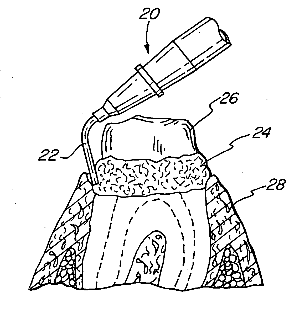
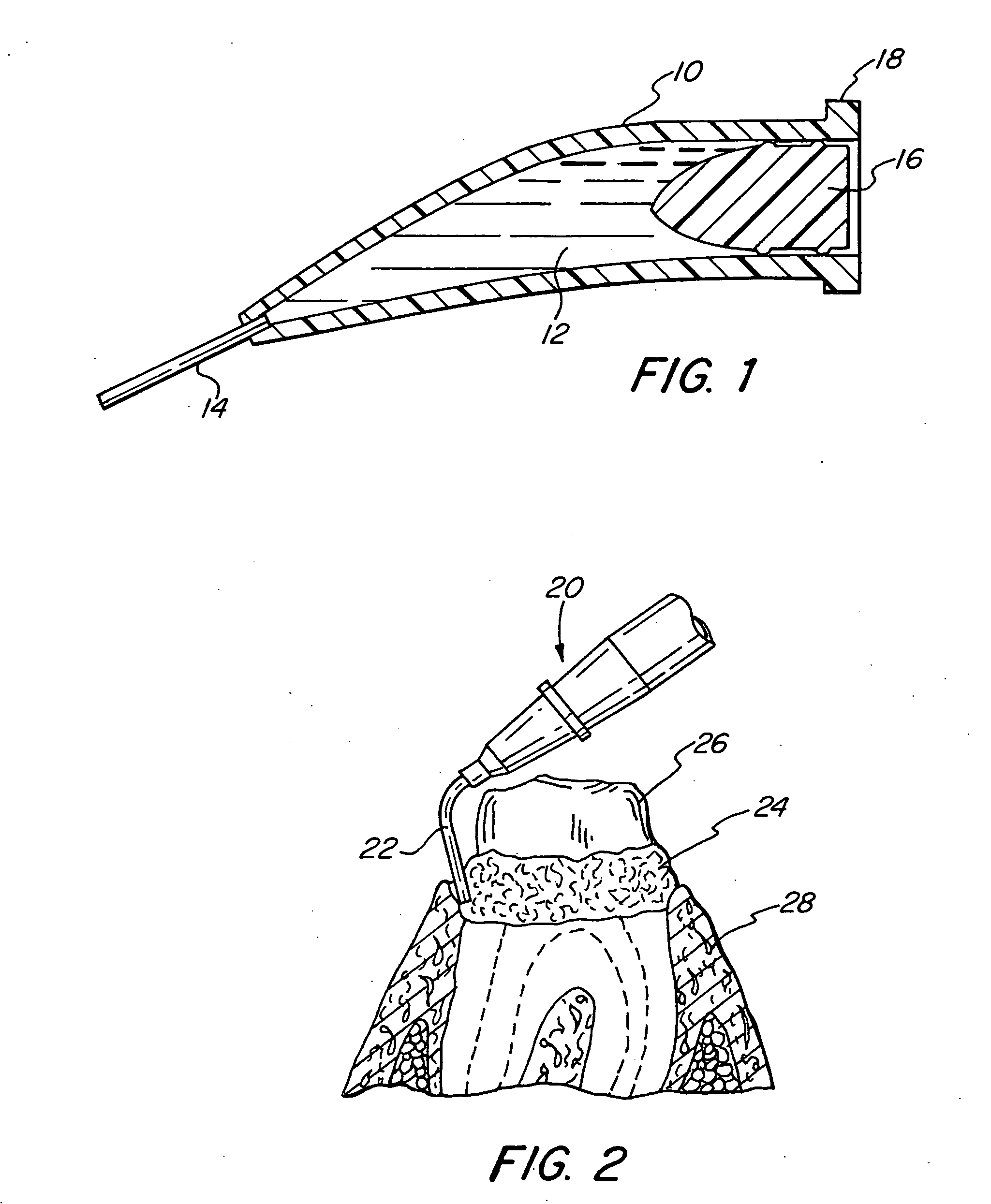
[0030]FIG. 1 schematically illustrates the present invention and retraction material of the present invention in a capsule 10. The capsule 10 aids in dispensing and placement of the retraction material 12 placed in the capsule 10. At the discharge end of the capsule 10 there may be placed a needle cannula 14, and at the other or loading end of the capsule 10 is a plug or piston 16. The plug or piston 16 is advanced toward the dispensing end to extrude the retraction material 12. A flange 18 is placed at the loading end to attach to a syringe or other device to displace the plug or piston 16. Preferable the syringe or other device has a mechanical advantage such as the manual extruder disclosed in U.S. Pat. No. 4,198,756 issuing to Dragan on Apr. 22, 1980, which is herein incorporated by reference. The syringe may also be of the type disclosed in U.S. Pat. No. 3,581,399 issuing to Dragan on Jun. 1, 1971, which is herein incorporated by reference.

[0031]FIG. 2 illustrates the technique...


PUM


Abstract

A retraction material promoting both retraction and drying of the gingival sulcus around a tooth. The retraction material comprises an astringent and an absorbing or drying agent. The retraction material is placed with a syringe and capsule around the gingival sulcus prior to the taking of an impression in a dental procedure.

Description

RELATED APPLICATIONS[0001]This application claims the benefit of U.S. Provisional Application No. 61 / 212,005 filed Apr. 6, 2009.[0002]This application is a continuation-in-part of application Ser. No. 11 / 825,802 filed Jul. 9, 2007, which is a continuation-in-part of Application No. PCT / US07 / 008,232 filed Mar. 30, 2007, which are herein incorporated by reference in their entirety.FIELD OF THE INVENTION[0003]The present invention relates in general to a retraction material used to retract gingiva in dentistry, and more particularly to a retraction material and system facilitating placement of the retraction material around the gingival sulcus.BACKGROUND OF THE INVENTION[0004]The traditional method for retracting gingival tissue prior to the taking of an impression of a prepared tooth to form a crown or bridge is to mechanically pack a small length of cord saturated with or without an astringent about the base of the tooth to enlarge the gingival sulcus space about the base of a tooth....

Claims


Application Information

Patent Timeline
IPC IPC(8): A61C5/14
CPCA61C9/0033A61C5/062A61C5/62
Inventor DRAGAN, WILLIAM B.
Owner CENTRIX
Learn More