Radio system and method for relaying radio signals with a power calibration of transmit radio signals

a radio signal and power measurement technology, applied in the direction of transmitter monitoring, transmission monitoring, modulation, etc., can solve the problems of no longer providing beam forming capabilities of the radio system, no means of monitoring the radio system, and deterioration of beam forming capabilities, so as to reduce manufacturing costs, simplify the manufacture of the transmit path, and improve the effect of power measuremen

Active Publication Date: 2010-10-07
TELEFON AB LM ERICSSON (PUBL)
View PDF12 Cites 155 Cited by
  • Summary
  • Abstract
  • Description
  • Claims
  • Application Information

AI Technical Summary

Benefits of technology

[0014]In the prior art it was necessary to adjust any attenuating and gain characteristics of the transmit paths very carefully by modifying the design of the radio system. The radio system as described herein enables a simple measurement of the transmit power levels. The attenuating and gain properties of the transmit paths can be monitored and adjusted if required during normal operation of the radio system. Therefore the manufacture of the transmit paths is simplified. The

Problems solved by technology

If the transmit power levels of the radio system are not set correctly, the beam forming will be deteriorated.
With a power amplifier in at least one of the transmit paths failing, the beam forming capabilities are no longer provided by the radio system.
Furthermore the prior art does not provide any means of monitoring the radio system to indicate whether or not all transmit paths are relaying according to prescribed transmit power levels other than the obvious provision of one power detector p

Method used


Image

  • Radio system and method for relaying radio signals with a power calibration of transmit radio signals
  • Radio system and method for relaying radio signals with a power calibration of transmit radio signals
  • Radio system and method for relaying radio signals with a power calibration of transmit radio signals

Examples


Embodiment Construction

[0029]The present invention will now be described on the basis of the drawings. It will be understood that the embodiments and aspects of the invention described herein are only examples and do not limit the protective scope of the claims in any way. The invention is defined by the claims and their equivalents. It will also be understood that features of one aspect can be combined with a feature of a different aspect.

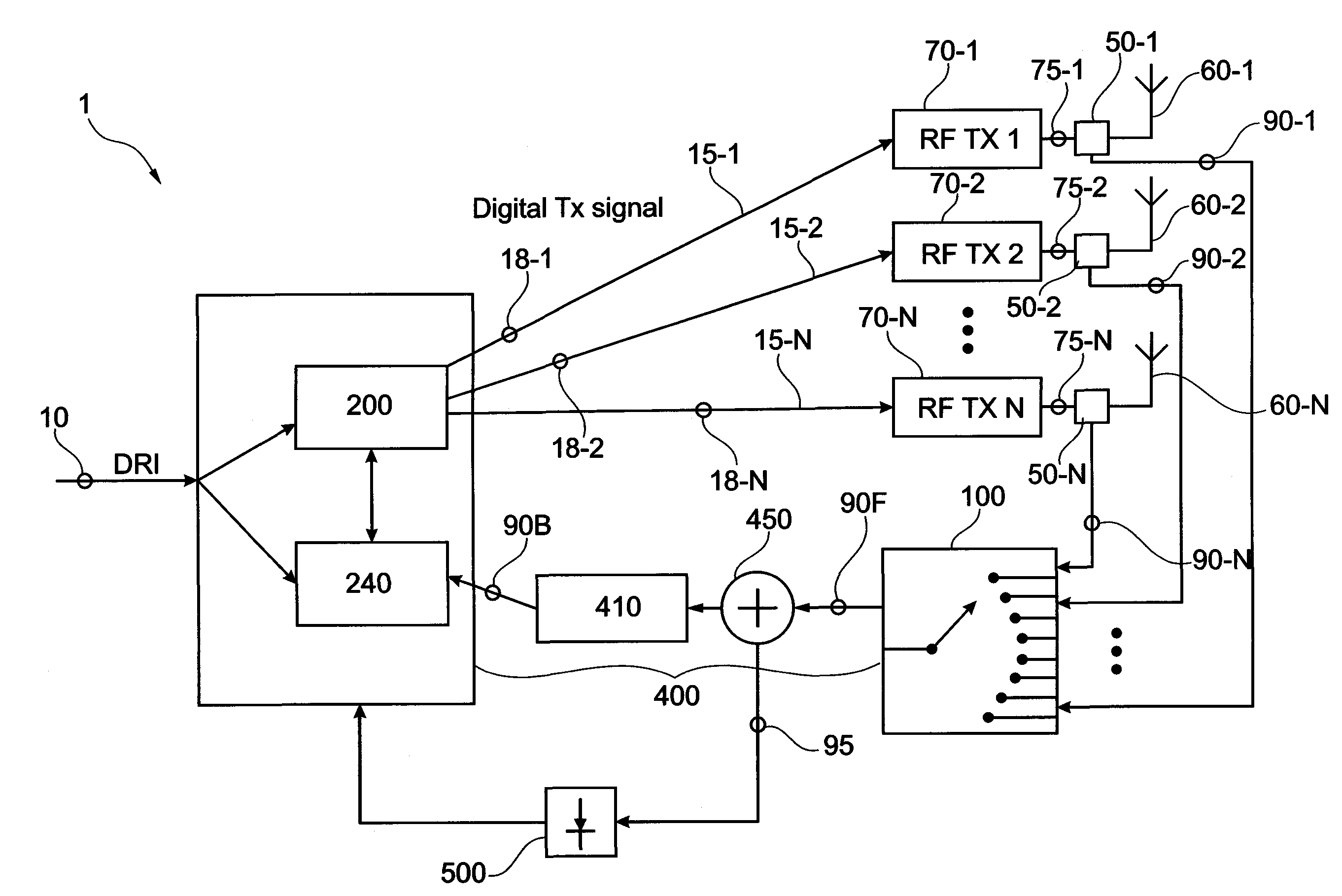
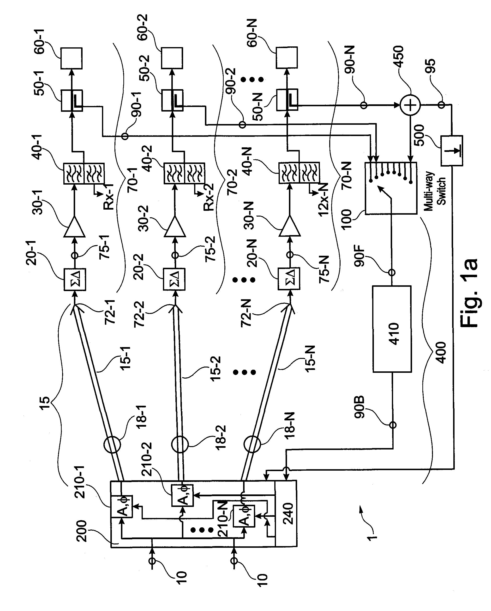
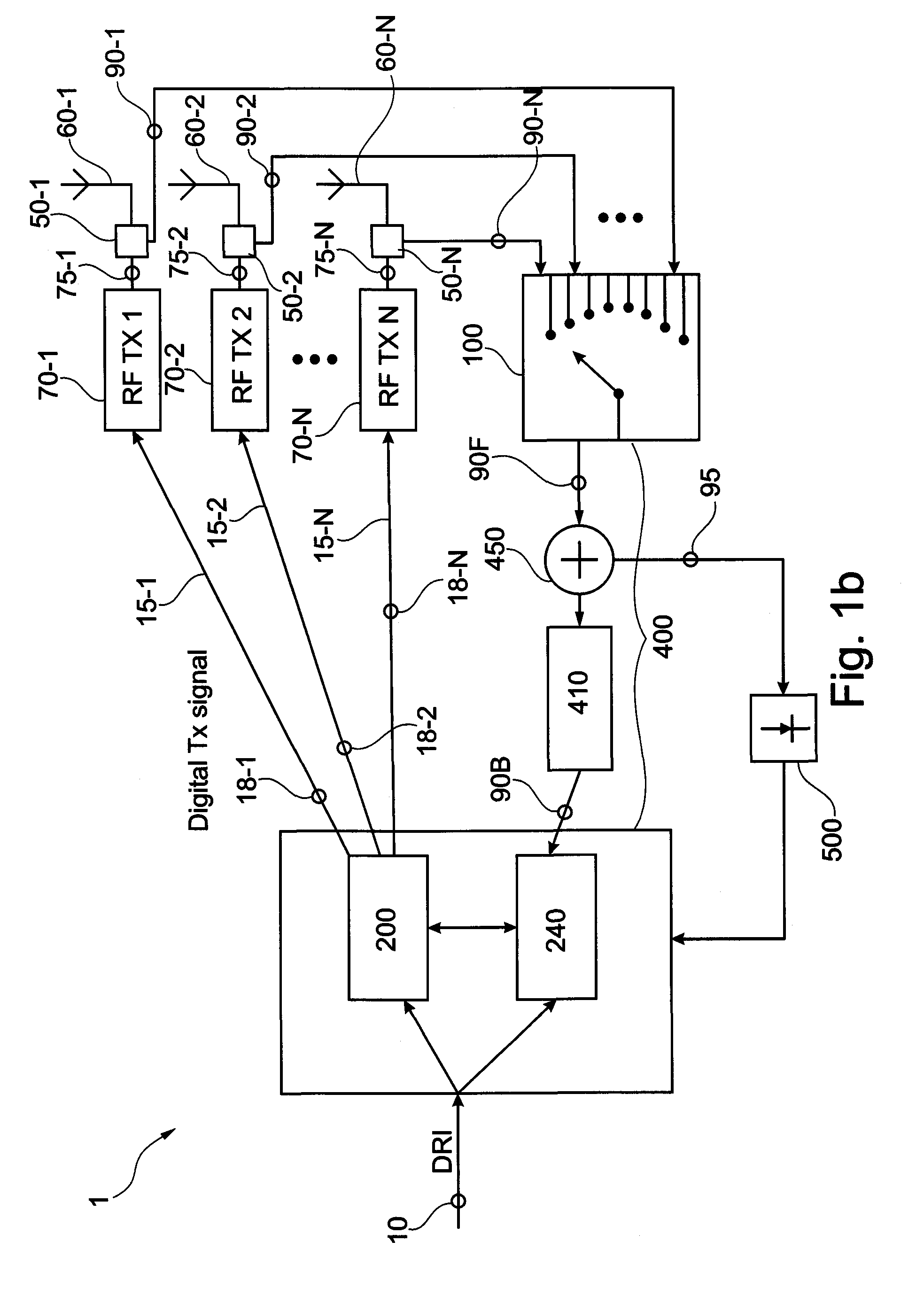
[0030]FIG. 1a shows a radio system 1. A payload signal 10 is forwarded to the radio system 1. Typically the payload signal 10 is provided in a format comprising an in phase component I and a quadrature component Q. The payload signal 10 is forwarded to a digital radio interface (DRI, see FIGS. 1b, 1c), as is known in the art. The digital radio interface may be implemented in one non-limiting aspect of the invention according to the open base station architecture initiative standard (OBSAI). A calibration unit 200 is adapted to split the payload signal 10 into at least o...


PUM


Abstract

The present invention provides a radio system and a method for relaying radio signals, providing a power calibration of transmit radio signals. With the radio system and the method no dedicated calibration signal generator is required for providing the power calibration of the transmit radio signals. The radio system comprises at least one transmit path, a calibration unit at the least one link and a power sensor. A selected one of coupled transmit signals is forwarded to a power sensor for measuring a power level of a portion of the selected one of the coupled transmit signals, wherein the calibration unit is adapted to update a power rating of the at least one transmit path in response to the transmit power level of the selected one of the coupled transmit signals.

Description

CROSS REFERENCE TO OTHER APPLICATIONS[0001]The present application is related to “A Radio System And A Method For Relaying Radio Signals” (Attorney's docket number 4424-P04841US00) filed concurrently on Apr. 1, 2009 and to “A Radio System And A Method For Relaying Radio Signals” (Attorney's docket number 4424-P04838US00) filed concurrently on Apr. 1, 2009 and to “A Radio System And A Method For Relaying Packetized Radio Signals” (Attorney's docket number 4424-P04839US00) filed concurrently on Apr. 1, 2009. The entire disclosure of each of the foregoing applications is incorporated herein by reference.FIELD OF THE INVENTION[0002]The field of the present invention relates to a radio system for relaying radio signals with a power measurement and power calibration of transmit radio signals. The field of the present invention further relates to a method for relaying radio signals with a power measurement and a power calibration of transmit radio signals. Furthermore, the field of the pre...

Claims


Application Information

Patent Timeline
IPC IPC(8): H04B17/02H04B17/40
CPCH04B17/10H01Q3/267
Inventor KENINGTON, PETER
Owner TELEFON AB LM ERICSSON (PUBL)
Why Eureka
Try Eureka