Electronic component mounting apparatus

Active Publication Date: 2010-10-14
PANASONIC CORP
View PDF2 Cites 12 Cited by
  • Summary
  • Abstract
  • Description
  • Claims
  • Application Information

AI Technical Summary

Benefits of technology

[0007]The present invention aims at providing an electronic component mounting apparatus that can eliminate a paste adhesive from a stamp pin without deterioration of productivity.
[0009]According to the present invention, a paste reservoir is embodied as a plurality of concentrically-arranged annular reservoirs, and one of the reservoirs is used as a test-stamping field. A necessity for providing a test-stamping field is obviated, and a distance over which the stamping head moves for test-stamping purpose can be shortened.

Problems solved by technology

The adhesive adheres to a substrate, which in turn becomes a cause for deteriorating stamp quality.
Therefore, the cleaning unit does not always situate at a position on a traffic line of the stamp head achieved during normal operation.
As a result, there arises a problem of movement of the stamp head involving consumption of time and deterioration of productivity.

Method used


Image

  • Electronic component mounting apparatus
  • Electronic component mounting apparatus
  • Electronic component mounting apparatus

Examples


Embodiment Construction

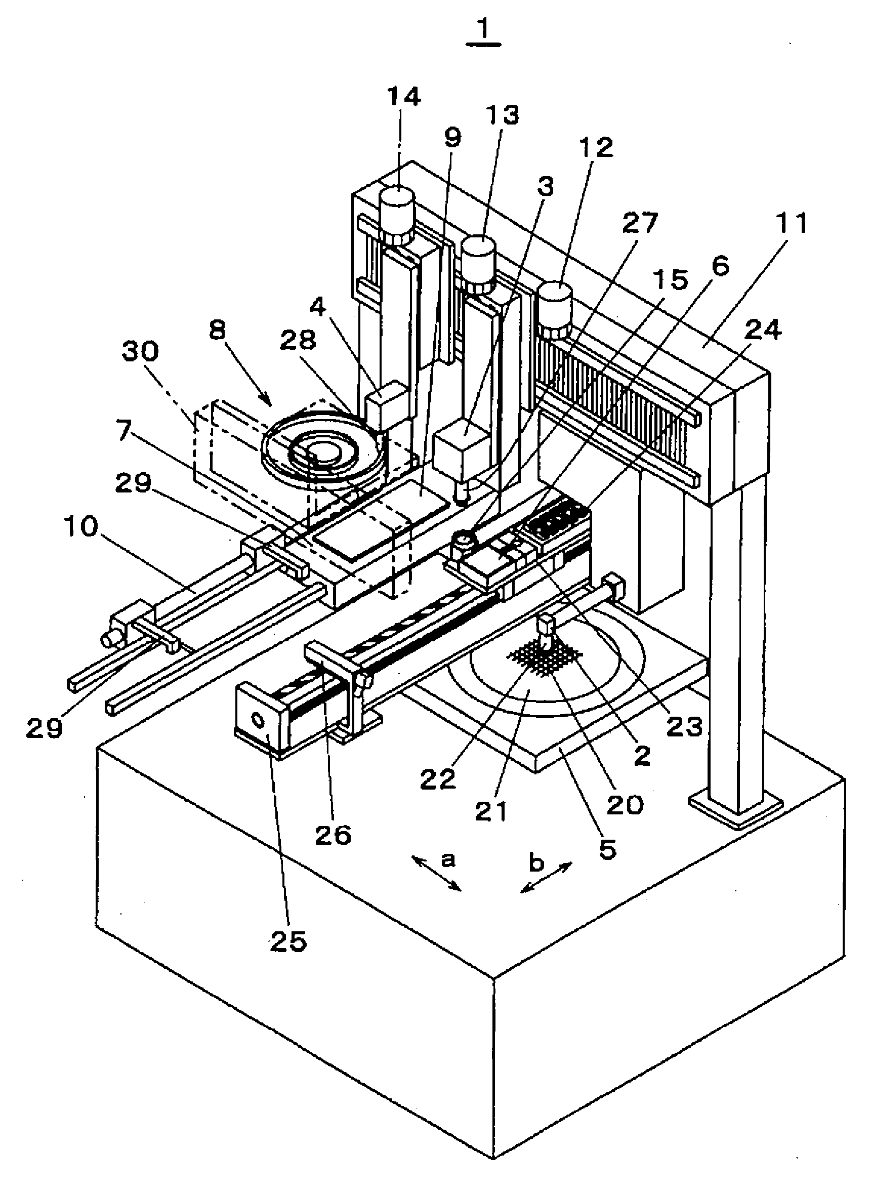
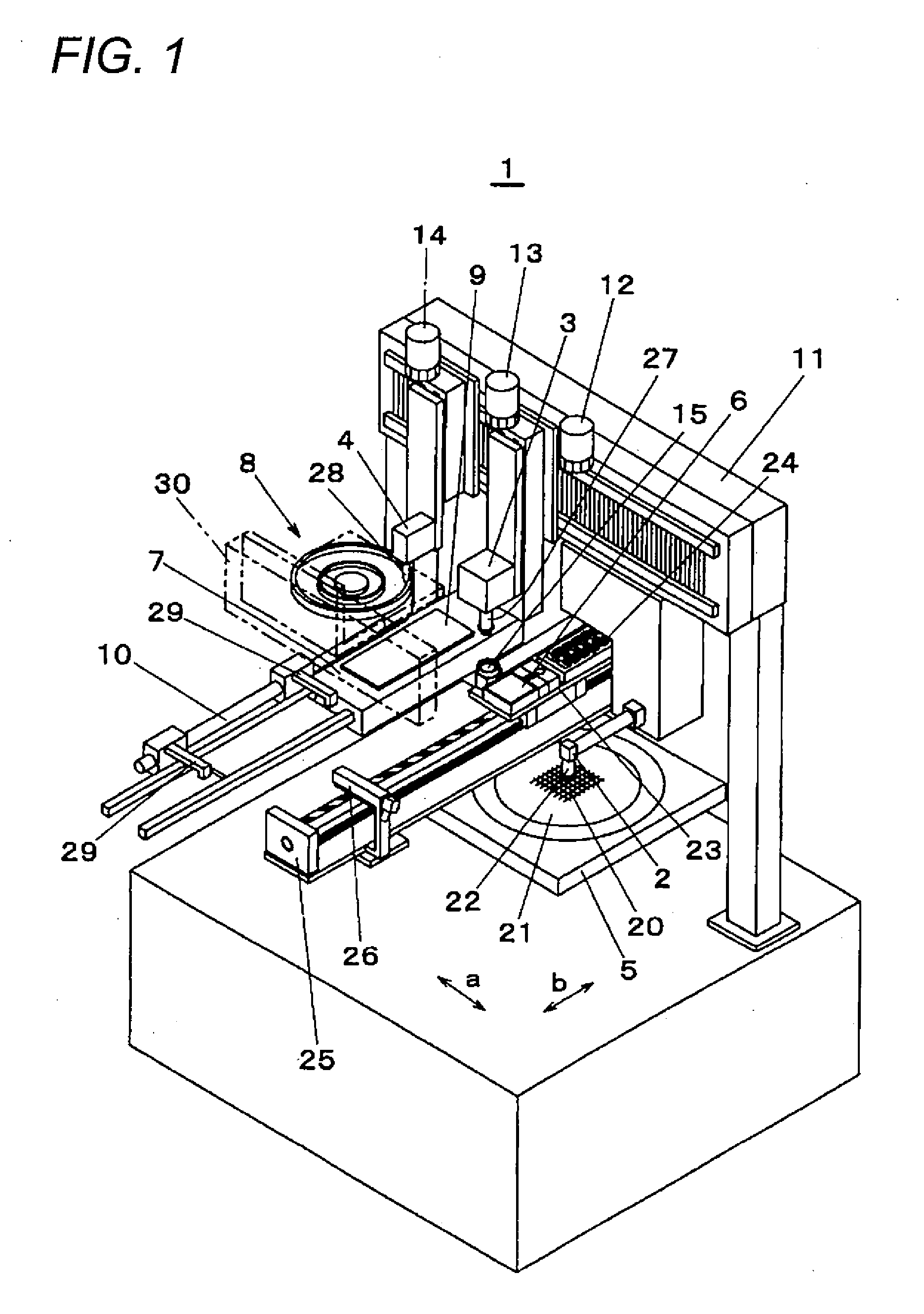
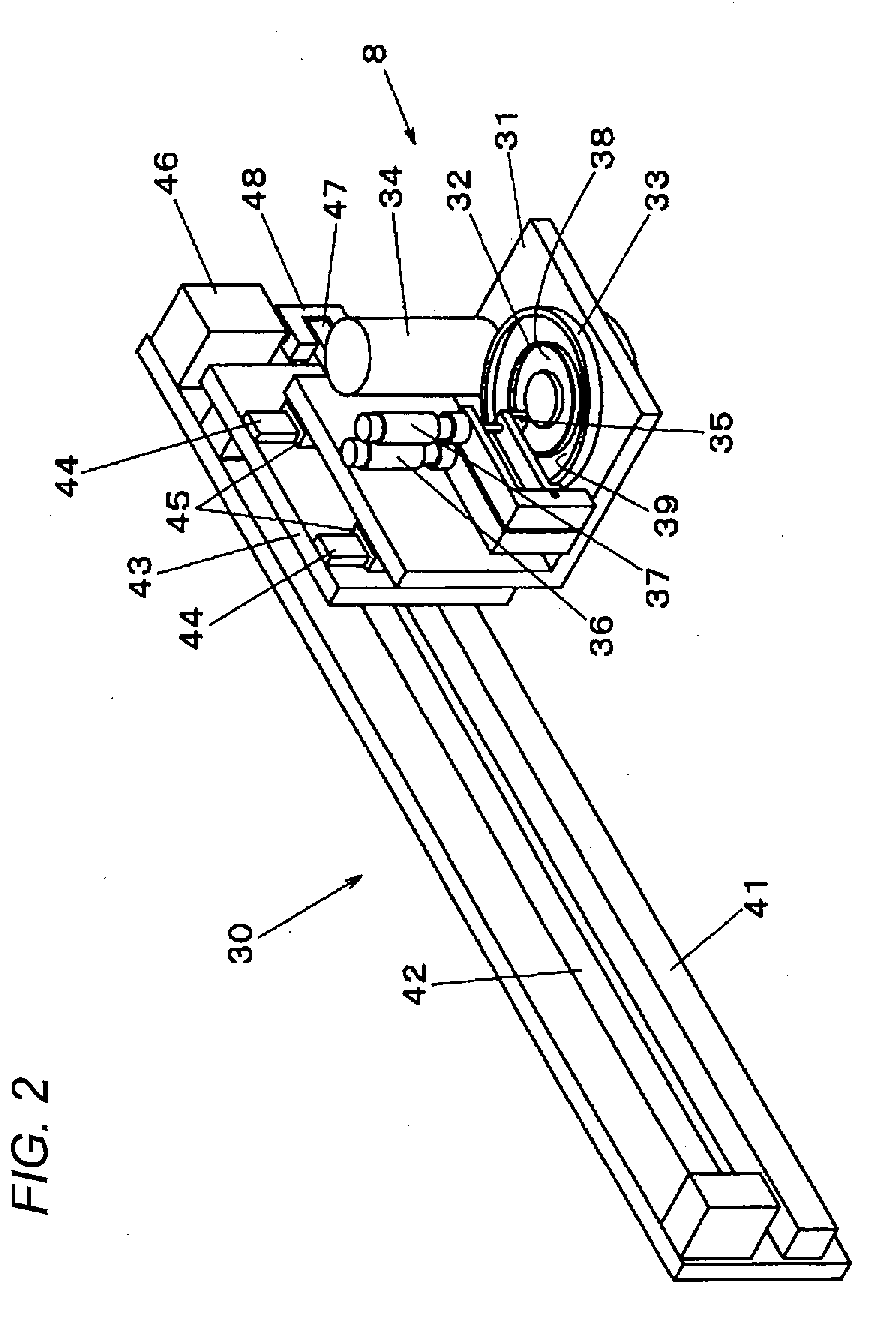
[0015]An embodiment of the present invention is now described by reference to the drawings. FIG. 1 is an oblique perspective view of an electronic component mounting apparatus of an embodiment of the present invention; FIG. 2 is an oblique perspective view of a paste supply section movement mechanism of the embodiment of the present invention; FIG. 3 is a plan view of the electronic component mounting apparatus of the embodiment of the present invention; FIG. 4 is a flowchart of test-stamping operation of the electronic component mounting apparatus of the embodiment of the present invention; and FIG. 5 is an oblique perspective view of a reservoir of the embodiment of the present invention.

[0016]As shown in FIG. 1, an electronic component mounting apparatus 1 includes, as principal portions, three working heads; namely, a pickup head 2, a bonding head 3, and a stamping head 4, and four working tables; namely, a component supply table 5, a component relay table 6, a mounting table 7,...


PUM

PropertyMeasurementUnit
Shapeaaaaaaaaaa

Abstract

Two concentrically-arranged annular reservoirs 32, 33 are placed at a position spaced away from a substrate 9 along a direction of movement of a stamping head 4, and the stamping head 4 is arranged so as to be able to linearly move between the reservoirs 32, 33 and the substrate 9. Paste is retained in the inner reservoir 32, and the outer reservoir 33 serves as a test-stamping field. The stamping head 4 performs paste stamping operation while moving between a position P1 set on the reservoir 32 and the substrate 9. A position P2 where test-stamping is performed is set on the reservoir 33 along a traffic line of the stamping head 4.

Description

BACKGROUND[0001]1. Field of the Invention[0002]The present invention relates to an electronic component mounting apparatus that mounts electronic components on a substrate with a paste adhesive stamped thereto.[0003]2. Description of the Related Art[0004]In a field of electronic components being mounted on a substrate, stamping a paste adhesive affixed to a stamping pin provided on a stamping head to the substrate has hitherto been known as a method for supplying the substrate with the paste adhesive. The stamping pin has a stamp surface for letting the paste adhesive adhere and stamping the thus-adhering adhesive to a substrate. Projections appropriate for a shape desired to be stamped are formed on the stamp surface. Although the paste adhesive adhering to the projection is stamped to the substrate, the paste adhesive builds up in space between the projections with an increase in the number of times stamp is performed. The adhesive adheres to a substrate, which in turn becomes a c...

Claims


Application Information

Patent Timeline
IPC IPC(8): H05K13/04
CPCH01L2224/743H01L24/81Y10T29/53178H01L2924/01006H01L2224/81801Y10T29/53174H01L2224/838H01L2224/83192H01L2924/3025H01L2924/01082H01L24/27H01L2924/01005H01L24/743H01L2924/01033H01L24/29H01L21/67144Y10T29/53183H01L24/83Y10T29/4913Y10T156/178
Inventor HIRAKI, TSUTOMU
Owner PANASONIC CORP
Why Eureka
Try Eureka