
Multilayer resonator and multilayer filter

Active Publication Date: 2010-10-14
MURATA MFG CO LTD
View PDF4 Cites 12 Cited by
  • Summary
  • Abstract
  • Description
  • Claims
  • Application Information

AI Technical Summary

Benefits of technology

[0015]The capacitor internal electrode arranged towards the side of the mounting surface is arranged so that the capacitor internal electrode does not overlap the mounting surface connected to the other capacitor internal electrode when viewed in plan view. Thus, almost no capacitance is generated between the capacitor internal electrode and the mounting surface electrode. The capacitance between these electrodes is unwanted from a design point of view of a resonator and a filter. Since such a capacitance is not generated, a capacitive component of the LC parallel resonant circuit is stable.
[0026]In accordance with various preferred embodiments of the present invention, the mounting surface connection via electrode connects the mounting surface electrode to the capacitor internal electrode, and the capacitor internal electrode arranged towards the side of the mounting surface is arranged so that the capacitor internal electrode does not overlap the mounting surface electrode connected to the other capacitor internal electrode when viewed in plan view. The capacitive component and the inductive component of the LC parallel resonant circuit are thus stabilized. The frequency characteristics of the resonator and filter are prevented from being degraded.

Problems solved by technology

There is a risk that the frequency characteristics of the multilayer filter 161 will be degraded.
There is also a risk that the frequency characteristics of the multilayer filter 161 will be degraded.

Method used


Image

  • Multilayer resonator and multilayer filter
  • Multilayer resonator and multilayer filter
  • Multilayer resonator and multilayer filter

Examples


Embodiment Construction

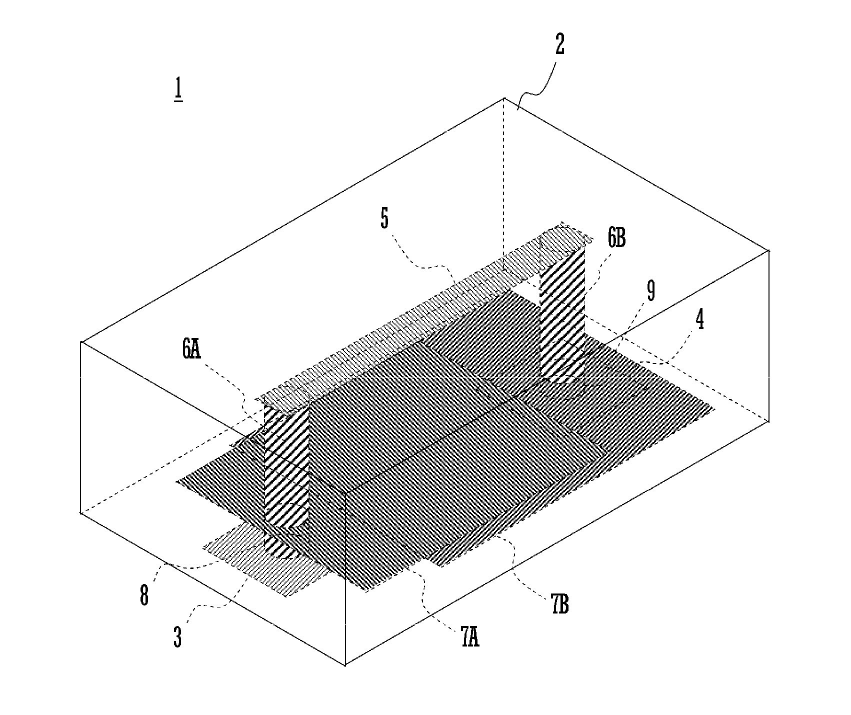
[0041]A multilayer resonator of a first preferred embodiment of the present invention is described below.

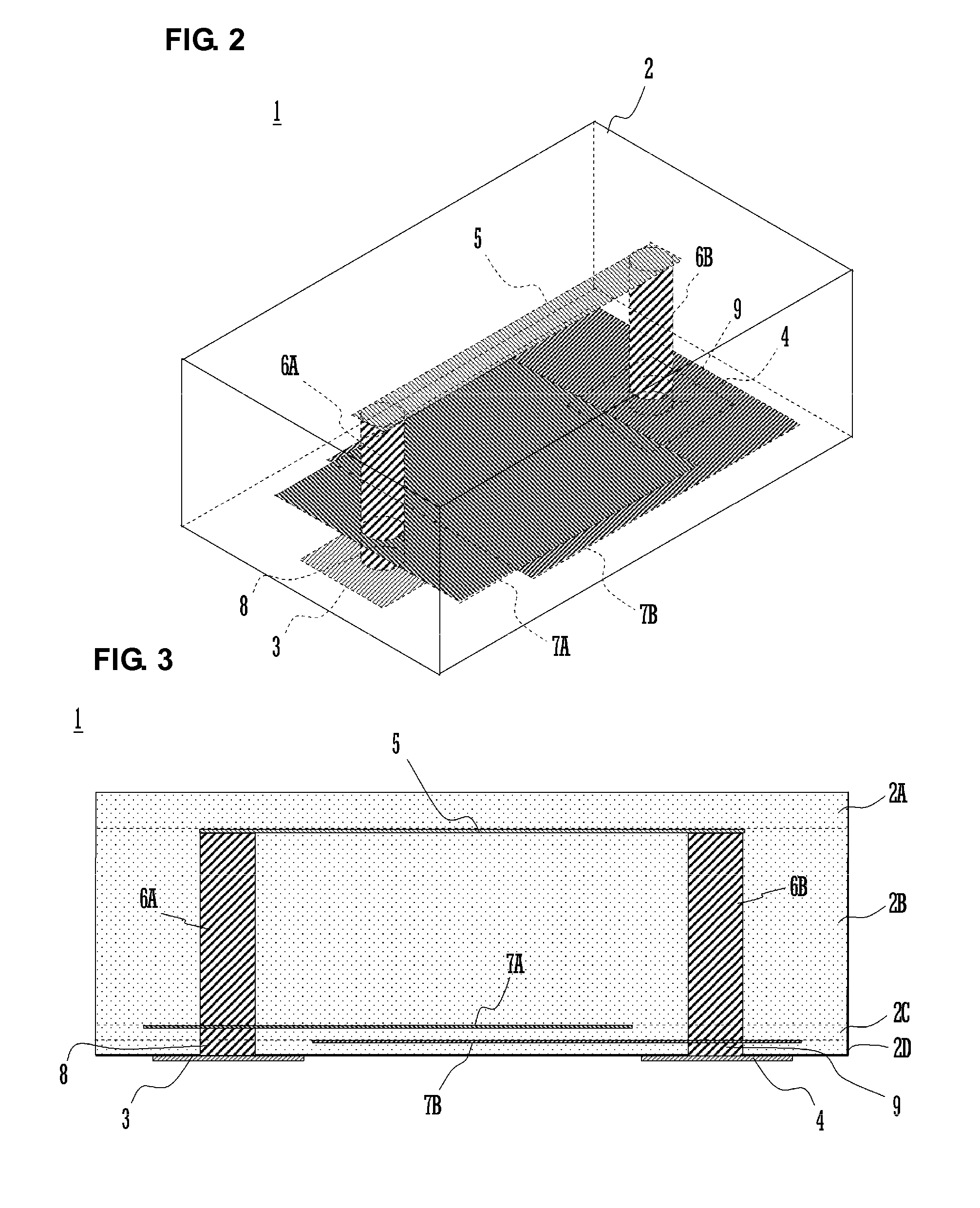
[0042]FIG. 2 is a see-through perspective view of the resonator, and FIG. 3 is a sectional view of the resonator.

[0043]The multilayer resonator 1 is configured as an LGA (Land Grid Array) package, and includes an input-output electrode and a ground electrode 4 disposed a mounting surface of a multilayer body 2. The surfaces of the multilayer body 2 other than the mounting surface thereof are covered with a metal layer (not shown). The ground electrode 4 corresponds to a first mounting surface electrode, and the input-output electrode 3 corresponds to a second mounting surface electrode.

[0044]The input-output electrode 3 and the ground electrode 4 are preferably produced by one of an application and firing process, a sputtering process, and a vapor deposition process, for example. For this reason, during the mounting of the multilayer resonator 1 to a mother board, a soldering ope...


PUM


Abstract

A multilayer filter includes a plurality of mutually coupled resonant circuits provided within a multilayer body. Capacitor internal electrodes, inductor internal electrodes, and inductor via electrodes, ground via electrodes, and input-output via electrodes are arranged within the multilayer body. The ground via electrodes and the input-output via electrodes are provided on a dielectric layer on a mounting surface, or a second dielectric layer on a first dielectric layer provided on the mounting surface. The capacitor internal electrodes arranged towards the side of the mounting surface do not overlap the input-output electrodes when viewed in plan view. With this configuration, degradation in frequency characteristics of a resonant circuit is effectively prevented by controlling one of an inductive component and a capacitive component of the resonant circuit.

Description

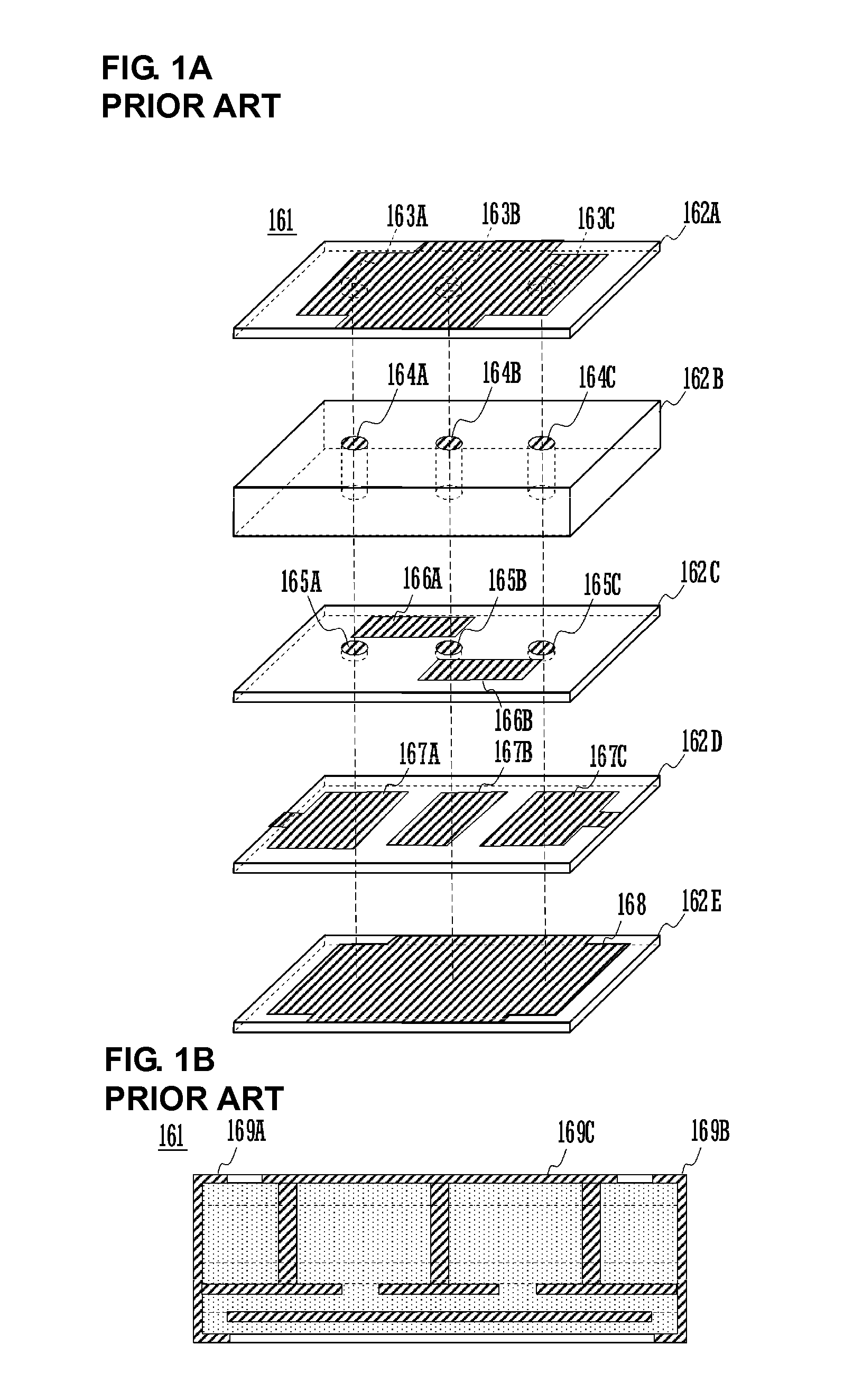
BACKGROUND OF THE INVENTION[0001]1. Field of the Invention[0002]The present invention relates to a multilayer resonator and a multilayer filter, each including a resonant circuit in a multilayer body defined by a laminate including a plurality of dielectric layers.[0003]2. Description of the Related Art[0004]A multilayer filter having a plurality of LC resonant circuits in a multilayer body defined by a laminate including a plurality of dielectric layers is used as a high-frequency filter. The LC resonant circuit may include a capacitor defined by opposed internal electrodes and an inductor defined by a via (for example, see Japanese Unexamined Patent Application Publication (Translation of PCT Application) No. 2000-165171).[0005]FIGS. 1A and 1B illustrate a known multilayer filter. FIG. 1A is a perspective view of the filter and FIG. 1B is a sectional view of the filter.[0006]A laminate including six layers of insulating sheets 162A-162E is arranged as the multilayer filter 161. Vi...

Claims


Application Information

Patent Timeline
IPC IPC(8): H01P7/10
CPCH03H5/02H03H7/09H03H7/0115H03H2001/0085H03H7/1783
Inventor NOSAKA, KOJI
Owner MURATA MFG CO LTD
Learn More