Method and device to enhance image quality in digital video processing systems using dithering

a technology of digital video processing and enhancing image quality, applied in the field of digital still image or moving image processing system, can solve the problems of introducing too noticeable image artifacts, introducing too noticeable flickering of images, and introducing too noticeable flickering, so as to improve the processing of image signals

Active Publication Date: 2010-10-14
BARCO NV
View PDF10 Cites 21 Cited by
  • Summary
  • Abstract
  • Description
  • Claims
  • Application Information

AI Technical Summary

Benefits of technology

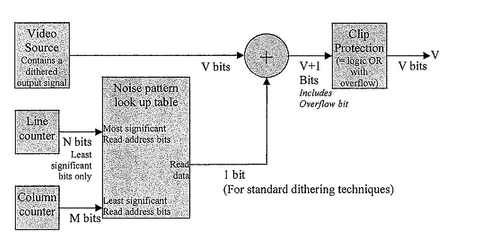
[0018]A first aspect of the present invention seeks to provide good, preferably improve processing of an image signal, where dithering pattern is applied in a processing chain.
[0022]This aspect of the invention provides a way of lessening the potentially disturbing spectral peaks in the dither pattern used in the processing chain by adding a well designed and proper amount of entropy to the video signal. Another way of considering the effect of this aspect of the invention is that it “fills up” the gaps in the spectrum in between the existing spectral peaks of the dither pattern. The resulting spectrum is a coloured (advantageously blue) noise spectrum. The continuity of the energy distribution helps to ensure interference-free image processing on such a treated dithered signal.
[0023]This aspect of the invention helps to eliminate undesired artifacts by adding well controlled entropy to the dithered image. This removes the undesired properties of the dithered image that cause the interferences and replaces the peaked spectrum by a more desirable continuous spectrum. In most cases a pattern offset dithering technique causes discrete spectral peaks where the energy increases with the frequency. Such an energy peaks can be considered as a fraction of a continuous coloured noise spectrum. This can be cyan, blue or purple noise or any other “cold” colour. Often the peak energy is proportional to the frequency. In that case the discrete peaks can be considered as samples from a blue noise spectrum. A digital signal can be generated and added to the dithered image such that a blue noise spectrum is obtained. A coloured noise spectrum is generated which is complementary to the peaked dithering spectrum such that when the two signals are mixed a continuous coloured noise spectrum is obtained. This eliminates potential interferences with other digital signal processing.
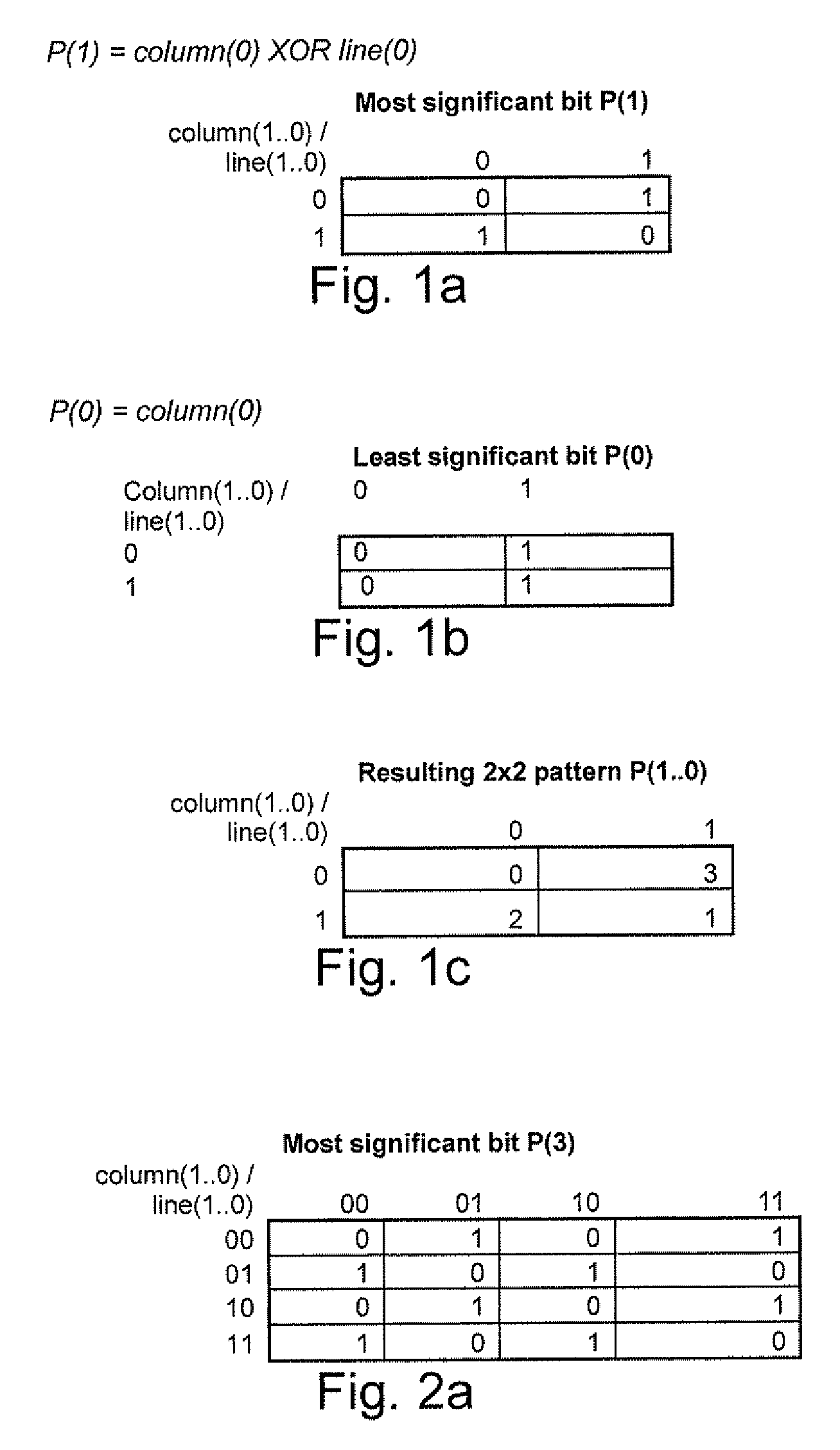
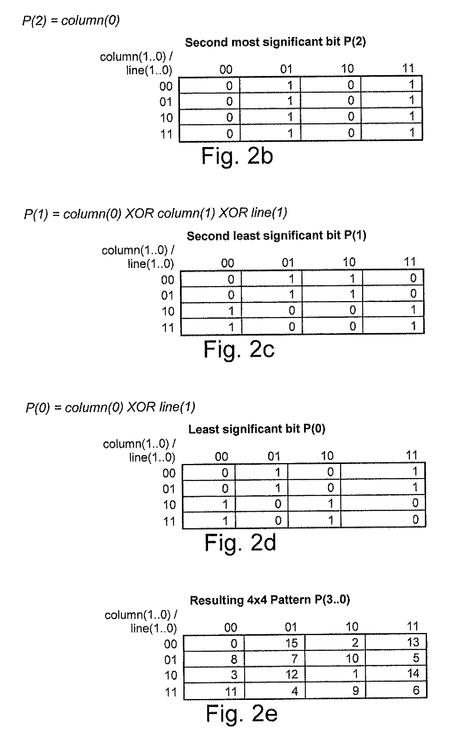
[0024]It will be appreciated that the noise pattern will not have a spectrum which is perfectly continuous but will, itself comprise a set of peaks. However, the peaks of the noise pattern advantageously are more closely spaced and more numerous compared to the spectrum of the dither pattern. This helps to complete the gaps in the spectrum of the dither pattern. The spectrum of the noise pattern can be made more continuous as the size of the noise pattern is increased. Advantageously, the dither pattern is an A×B array of offset values which is tiled across the image and the noise pattern is an N×M array of offset values which is tiled across the image, where N×M>A×B.
[0035]Using a noise pattern with these properties as a dither pattern in image processing has been found to result in a processed image signal with a more continuous spectrum. This helps to reduce undesirable artifacts when the processed signal is subsequently processed by other processing stages in an image processing chain. Advantageously, the noise pattern is applied before a colour bit depth reduction operation.

Problems solved by technology

Larger patterns can introduce too noticeable image artifacts, such as disturbing patterns or interferences with image details.
Slower periodical modulations can introduce too noticeable flickering of the image.
The pattern is temporally modulated in order to reduce the spatial visibility of the pattern but the disadvantage is potentially some slightly visible flickering when using such a temporally varying pattern as an offset to the video data prior to truncation.
Therefore temporal modulation of the pattern is not always desirable.
Some processing functions, such as digital filters or interpolations, can interfere with the dithering patterns and artifacts such as false contouring and / or banding can become clearly visible.
Accordingly, it is not possible for a user to control the interference effects that occur in the image processing chain.

Method used


Image

  • Method and device to enhance image quality in digital video processing systems using dithering
  • Method and device to enhance image quality in digital video processing systems using dithering
  • Method and device to enhance image quality in digital video processing systems using dithering

Examples


Embodiment Construction

[0063]The present invention will be described with respect to particular embodiments and with reference to certain drawings but the invention is not limited thereto but only by the claims. The drawings described are only schematic and are non-limiting. In the drawings, the size of some of the elements may be exaggerated and not drawn on scale for illustrative purposes. Where the term “comprising” is used in the present description and claims, it does not exclude other elements or steps. Furthermore, the terms first, second, third and the like in the description and in the claims, are used for distinguishing between similar elements and not necessarily for describing a sequential or chronological order. It is to be understood that the terms so used are interchangeable under appropriate circumstances and that the embodiments of the invention described herein are capable of operation in other sequences than described or illustrated herein.

White Noise Generation

[0064]A computer program ...


PUM


Abstract

A processing chain for a digital image signal (12) applies a dither pattern (14), having a first spectrum, to the image signal at a point in the processing chain. A further noise pattern (10) is applied to the image signal during the processing chain. The noise pattern (10) has a second spectrum which is configured such that the combination of the first spectrum and second spectrum results in a more continuous spectrum. Another aspect describes a noise pattern (10) which can be used as an offset dither pattern for digital images, especially before colour bit depth reduction. The noise pattern comprises an array of values which are linearly distributed across a range, with each value in the range occurring an equal number of times. Similar values at extreme ends of the range of values are dispersed within the array. The pattern has a Poisson-disk two-dimensional spectral energy distribution. Values are positioned in the array based on distance to similar values in neighbouring repetitions of the array. The array has “magic square” properties.

Description

FIELD OF THE INVENTION[0001]The present invention relates to digital still image or moving image processing systems where dither is applied to a digital image signal.BACKGROUND TO THE INVENTION[0002]Whenever the bit depth of an image needs to be reduced in a digital system a technique called dithering can be used to represent the original high bit depth image by fewer bits. The idea behind this is that by introducing small modulations to the image signal, before the truncation operation, the image signal after truncation to a lower bit depth will have a correct average value in an area as small as possible and / or a period as small as possible. A widely used technique is offset pattern dithering which can be implemented with relatively simple circuitry and which has predictable and reliable results.[0003]Typically the size of the offset dither pattern is 2×2 or 4×4 pixels and the optional periodic modulation of these patterns occurs over 2 or 4 frames. Larger patterns can introduce t...

Claims


Application Information

Patent Timeline
Patent Type & Authority Applications(United States)
IPC IPC(8): G09G5/02
CPCH04N5/21G06T11/001G09G3/2044
Inventor VAN BELLE, RONNY
Owner BARCO NV
Why Eureka
Try Eureka