

Wind turbine blade with submerged boundary layer control means comprising crossing sub-channels
- Summary
- Abstract
- Description
- Claims
- Application Information
AI Technical Summary
Benefits of technology
Problems solved by technology
Method used
Image

Examples
first embodiment
[0046]FIG. 3 shows a schematic view of a boundary layer control means 100 for maintaining flow of a flowing medium attached to the exterior of a flow control member, such as a wind turbine blade, having a flow control surface 112. The boundary layer control means 100 comprises a channel, which is submerged in the flow control surface 112. The channel extends in the direction of a free flow having a flow direction, which is depicted with arrows in the figure. The channel comprises a first end 102 facing the free flow and a second end 104 positioned downstream in the flow of the flowing medium from the first end 102. The channel further comprises a bottom surface 106 extending from the first end 102 to the second end 104.
[0047]The channel comprises a first channel zone 122 at the first end 102 of the channel, and a second channel zone 124 at the second end 104 of the channel. The first channel zone 122 comprises a first sub-channel 118 and a second sub-channel, both of which are adapt...
fourth embodiment
[0060]In the numerals, x refers to a particular embodiment. Thus, for instance 402 refers to the first end of the
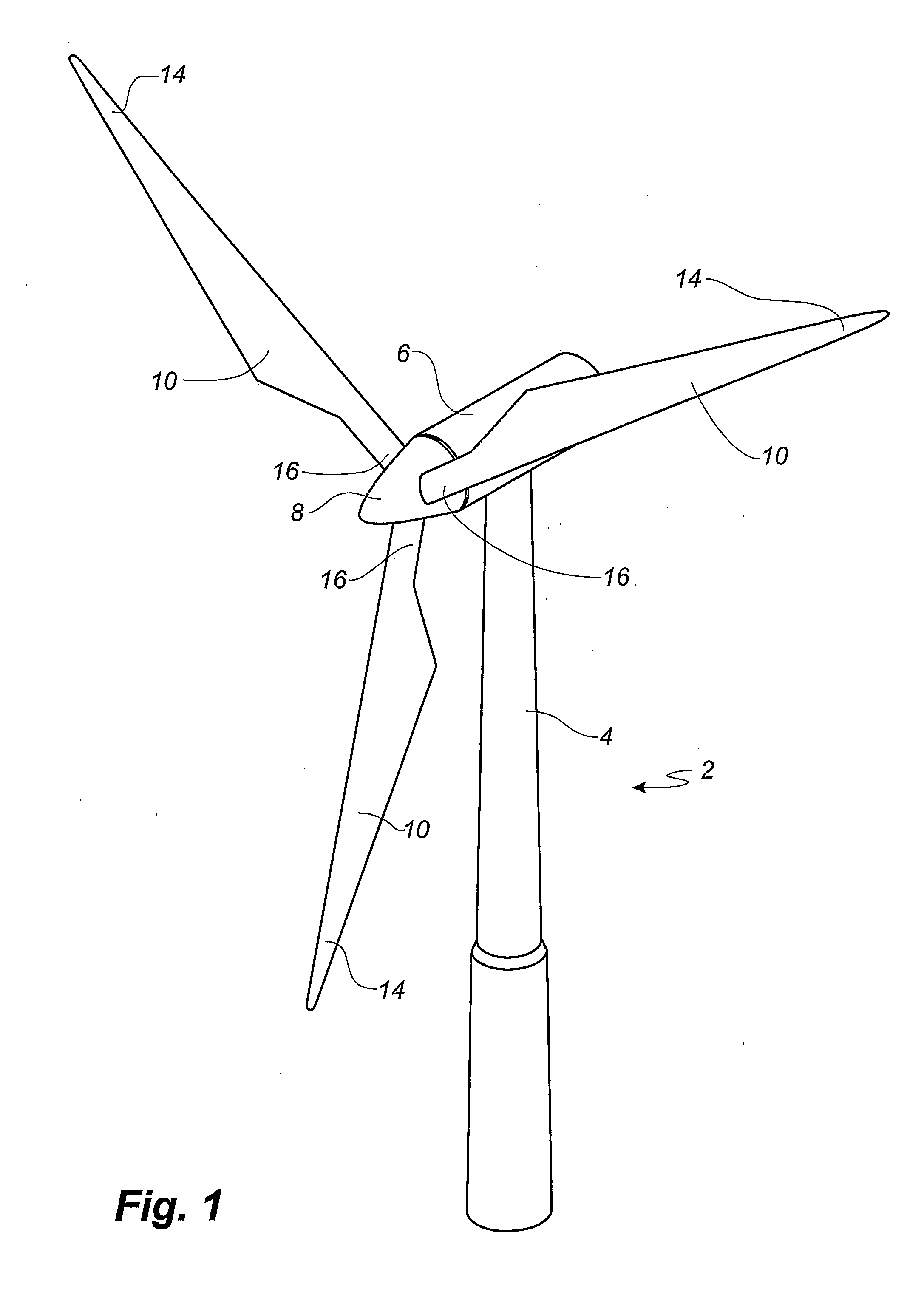
[0061]2 wind turbine
[0062]4 tower
[0063]6 nacelle
[0064]8 hub
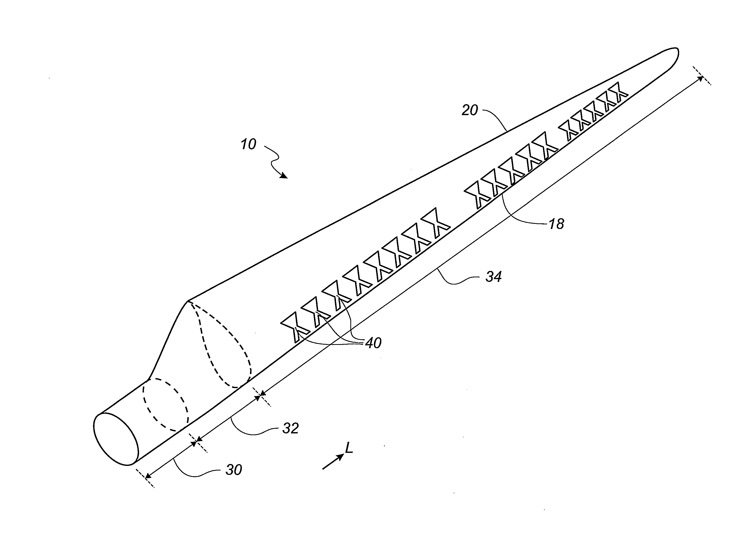
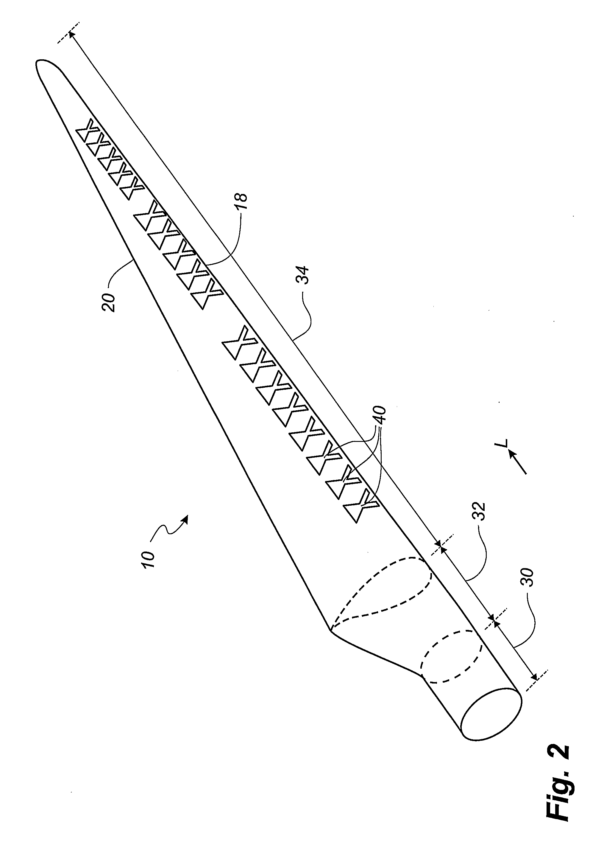
[0065]10 blade
[0066]14 blade tip
[0067]16 blade root
[0068]18 leading edge
[0069]20 trailing edge
[0070]30 root region
[0071]32 transition region
[0072]34 airfoil region
[0073]40 boundary layer control means
[0074]60, 62 lips
[0075]64 first bottom edge
[0076]66 second bottom edge
[0077]x00 boundary layer control means
[0078]x02 first end
[0079]x04 second end
[0080]x06 bottom surface
[0081]x08 first sidewall
[0082]x10 second sidewall
[0083]x12 flow control surface
[0084]x18 first sub-channel
[0085]x20 second sub-channel
[0086]x22 first channel zone
[0087]x24 second channel zone
[0088]x32 set of vortices
PUM
 Abstract
Description
Claims
Application Information