Vibrating prilling bucket for granulation of a fluid substance

a fluid substance and vibrating technology, applied in the direction of granulation by liquid drop formation, granulation using vibration, auxillary shaping apparatus, etc., can solve the problems of difficult to predict the negative or positive influence of any structural modification of the bucket, the process involving the formation and break-up of the liquid jet is quite complex, and the good monodispersion of the droplets is difficult to obtain, etc., to achieve less severe mechanical stress, improve reliability, and improve the effect of monodisper

Inactive Publication Date: 2010-10-14
UREA CASALE SA
View PDF4 Cites 2 Cited by
  • Summary
  • Abstract
  • Description
  • Claims
  • Application Information

AI Technical Summary

Benefits of technology

[0025]The inventions has a number of advantages. It has been found that monodispersion of droplets is improved by the “pure” vertical vibration provided by the invention, compared to a known prilling bucket wherein the vibrating engine is unbalanced, and vibrations are transmitted also in directions other than the main axis of vibration, or discharged to the supports of the bucket and / or the shaft.
[0026]Furthermore, the invention results in a less severe mechanical stress of the supports and bearings of prilling bucket. Reduced stress improves the reliability and makes easier the achievement of higher rotating speed and / or higher frequency of vibration, as required especially in large-capacity units.
[0027]Another advantage is that the balanced vibration can be obtained with low-cost and commonly available vibrating units, for example pneumatic turbine vibrators, requiring no or minor modification for use in the prilling bucket according to the invention.

Problems solved by technology

It should be noted that good monodispersion of the droplets is difficult to obtain, and for some products (such as urea) uniform size and shape of the solid granules dramatically influences the value of the product.
The process involving formation and break-up of the liquid jets is quite complex and is not easy to foresee the negative or positive influence of any structural modification of the bucket.
So, the realization and optimization of a prilling bucket is a challenging task, and a continuous need is felt to improve the known technique.

Method used


Image

  • Vibrating prilling bucket for granulation of a fluid substance
  • Vibrating prilling bucket for granulation of a fluid substance
  • Vibrating prilling bucket for granulation of a fluid substance

Examples


Embodiment Construction

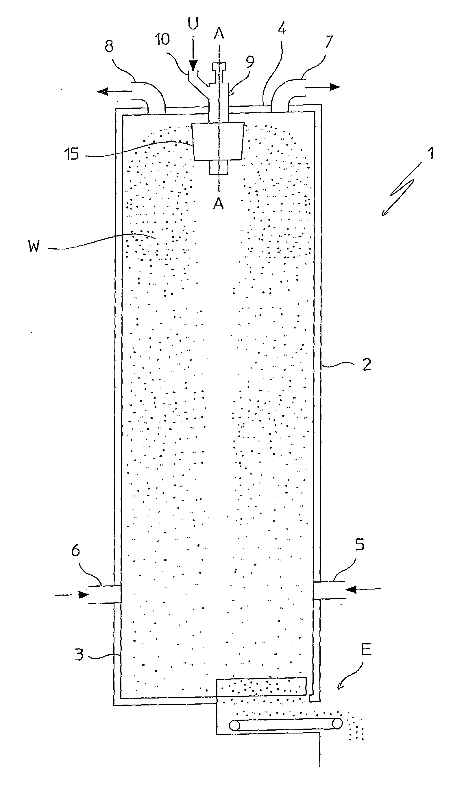
[0034]With reference to FIG. 1, a prilling tower 1 is shown, having a cylindrical shell 2 with vertical axis A-A closed by a base plate 3 and a top wall 4.

[0035]Ducts 5 and 6 are provided near base plate 3, for input of a continuous rising flow of a cooling medium (for example air) through tower 1. Ducts 7 and 8 are provided at the top wall 4 for discharging said cooling medium.

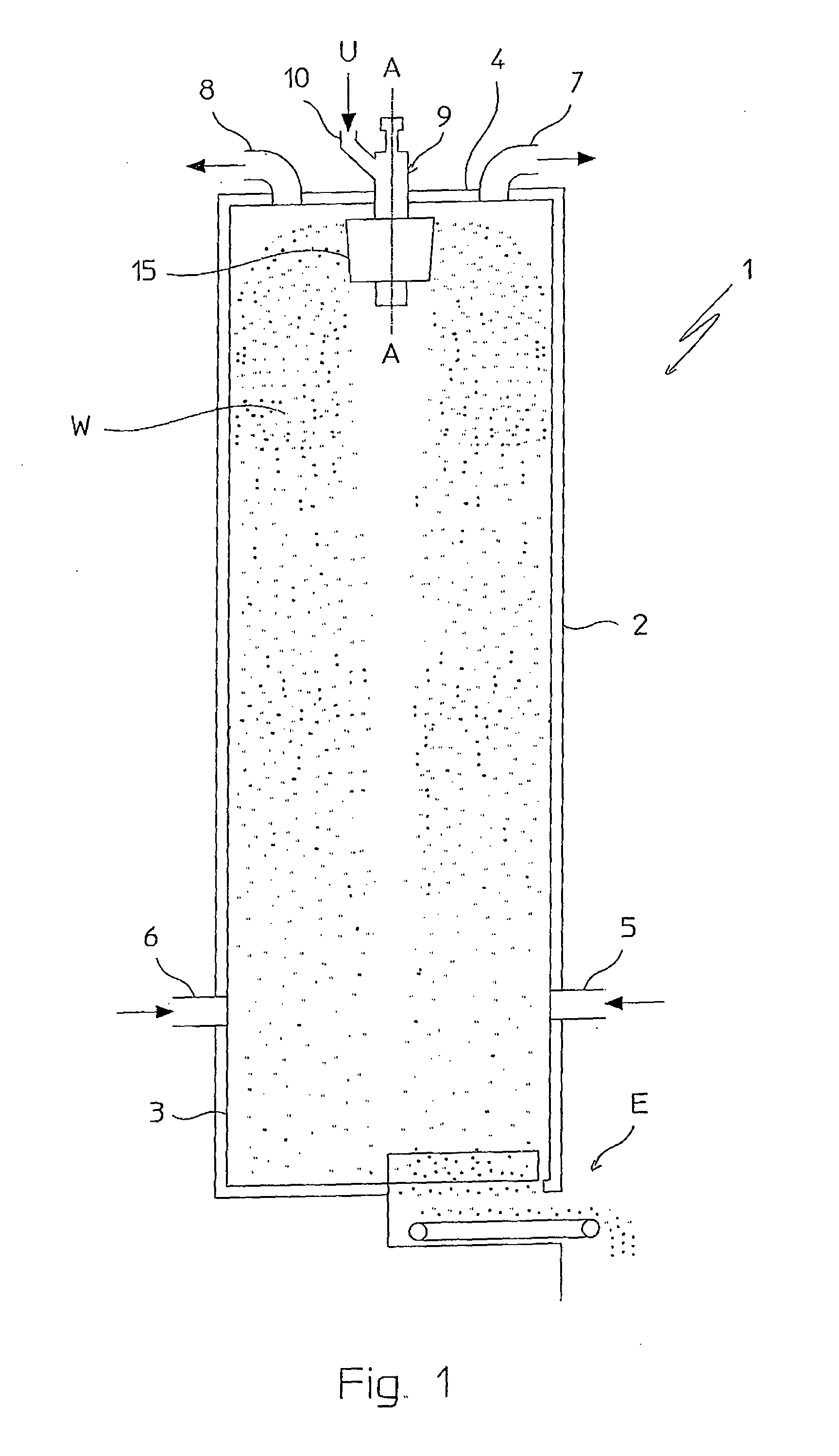
[0036]A fluid substance U to be granulated is fed to a prilling bucket 15 installed at top of the tower 1. In operation, the prilling bucket 15 is rotated around axis A-A and vibrated according to direction of the same axis A-A, producing a downward flow W of droplets of substance U, which are cooled by the rising cooling air until they solidify into spherical or substantially spherical granules. Solid granules are discharged through a bottom aperture E.

[0037]More in detail, the fluid substance U is fed through a feeding duct 10 connected to an axial duct 9 crossing the top wall 4. The droplets of said substa...


PUM

PropertyMeasurementUnit
temperatureaaaaaaaaaa
vibration-driving forceaaaaaaaaaa
forcesaaaaaaaaaa

Abstract

A vibrating and rotating prilling bucket (15) for granulation of a fluid substance (U), said bucket (15) comprising a perforated side wall (15a) and vibrating devices (51, 52) arranged to deliver a force with constant direction (A-A). In a preferred embodiment, the vibrating unit comprise two counter-rotating vibrators delivering rotating forces which balance each other perpendicularly to said constant direction (A-A).

Description

FIELD OF APPLICATION[0001]The present invention relates to a prilling bucket for the granulation of a fluid substance.[0002]The term prilling bucket is used with reference to a bucket with a perforated side wall, to be mounted inside a prilling tower, fed with said liquid substance and rotated at a suitable speed, so that a flow of droplets of said fluid substance is ejected through the perforated side wall.PRIOR ART[0003]It is known art to convert a given fluid substance into solid granules by means of a prilling tower wherein small droplets of the fluid substance flow downward and in countercurrent to a cooling medium, e.g. air. The small droplets are solidified under the action of the cooling medium and spherical or quasi-spherical granules are obtained. Prilling towers are used for example at the end stage of an urea plant, where liquid urea, with high degree of purity, is solidified into granules which constitute the final product.[0004]A known way of producing said flow of sma...

Claims


Application Information

Patent Timeline
Patent Type & Authority Applications(United States)
IPC IPC(8): B29B9/00
CPCB01J2/18B01J2/04
Inventor RIZZI, ENRICO
Owner UREA CASALE SA
Why Eureka
Try Eureka