Methods and Systems for Loading a Stent

a stent and stent technology, applied in the field of braided stents, can solve the problems of reducing the radial strength of the stent,

Inactive Publication Date: 2010-10-14
MEDTRONIC VASCULAR INC
View PDF9 Cites 130 Cited by
  • Summary
  • Abstract
  • Description
  • Claims
  • Application Information

AI Technical Summary

Problems solved by technology

Soon after the procedure, however, a significant proportion of treated vessels re-narrow.
Unfortunately, braided stents often undergo stress relaxation in the delivery system prior to deployment, leading to a smaller post-deployment diameter.
This may result in a lack of radial strength to prop open the vessel lumen.
Unfortunately, this increases the crossing profile of the compressed stent, reducing maneuverability and the ability to deploy the stent in smaller vessels.

Method used


Image

  • Methods and Systems for Loading a Stent
  • Methods and Systems for Loading a Stent
  • Methods and Systems for Loading a Stent

Examples


Embodiment Construction

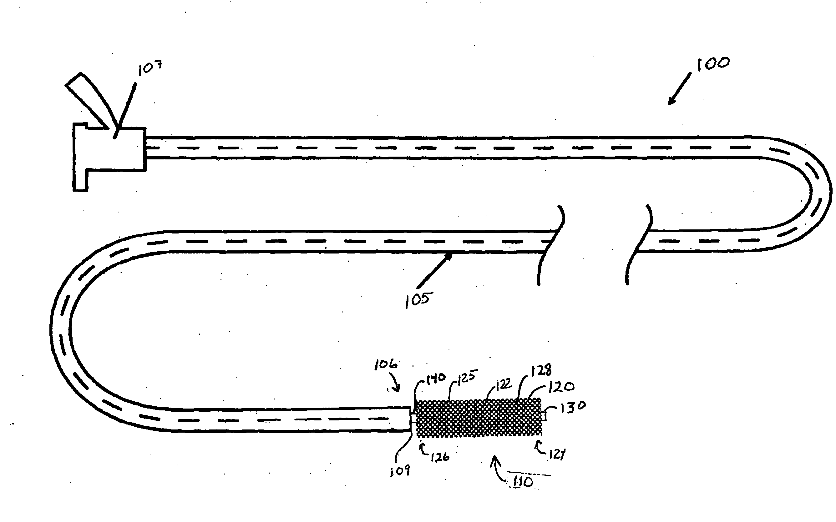
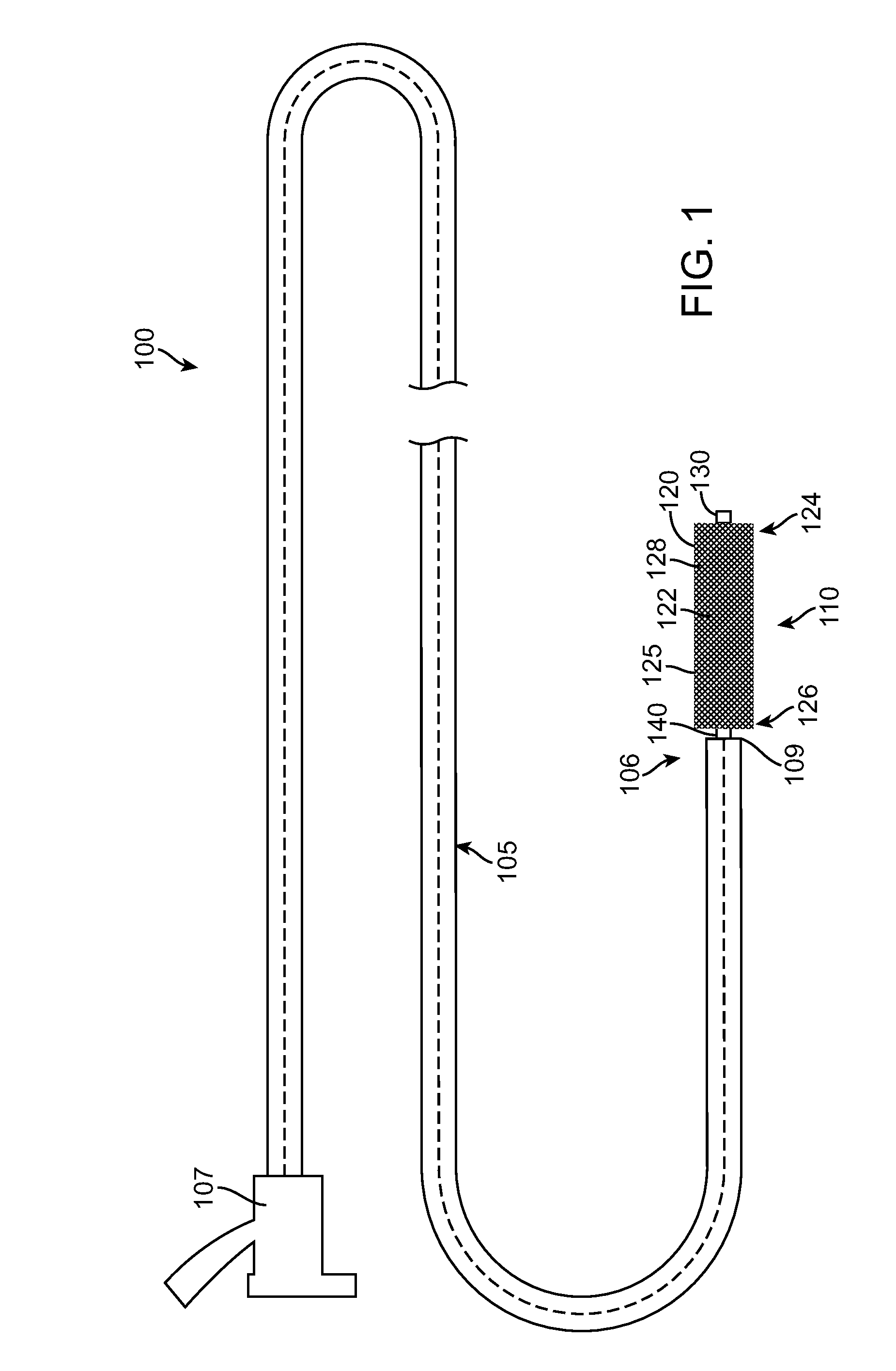
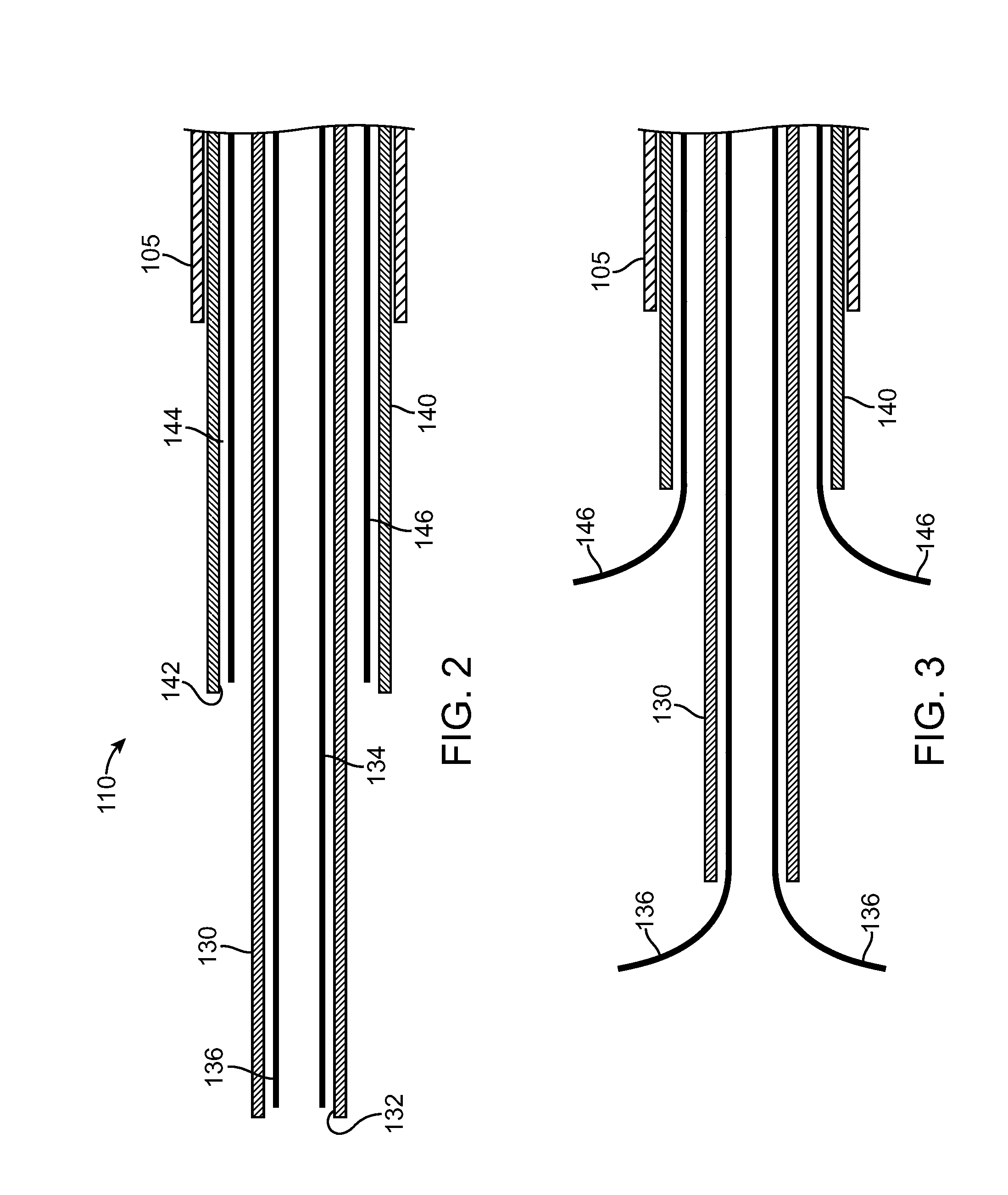
[0027]The invention will now be described by reference to the figures wherein like numbers refer to like structures. The terms “distal” and “proximal” are used herein with reference to the treating clinician during the use of the catheter system; “Distal” indicates an apparatus portion distant from, or a direction away from the clinician and “proximal” indicates an apparatus portion near to, or a direction towards the clinician.

[0028]FIGS. 1 to 42 illustrate various embodiments of braided stent loading and delivery systems and methods of using the stent loading and delivery systems in accordance with the present invention. The various embodiments illustrated each show a braided stent delivery system having a stent loading assembly for loading a stent into a delivery catheter just prior to insertion into a patient's vascular system.

[0029]FIG. 1 is a side view of a stent loading and delivery system 100 made in accordance with the present invention. In this embodiment, the polymeric st...


PUM


Abstract

A stent loading and delivery system includes a delivery catheter having a catheter lumen, a stent loading assembly adjacent a distal end of the delivery catheter, and a braided stent disposed on the stent loading assembly. The stent loading assembly is configured to retain the stent in an expanded state until just prior to insertion into a patient at which time the stent loading assembly elongates and compresses the stent into a delivery configuration.

Description

TECHNICAL FIELD[0001]The technical field of this disclosure is medical implant devices, particularly, braided stents.BACKGROUND OF THE INVENTION[0002]Stents are generally cylindrical shaped devices that are radially expandable to hold open a segment of a blood vessel or other anatomical lumen after implantation into the body lumen. Stents have been developed with coatings to deliver drugs or other therapeutic agents.[0003]Stents are used in conjunction with balloon catheters in a variety of medical therapeutic applications including intravascular angioplasty. For example, a balloon catheter device is inflated during PTA (percutaneous transluminal angioplasty) to dilate a stenotic blood vessel. The stenosis may be the result of a lesion such as a plaque or thrombus. After inflation, the pressurized balloon exerts a compressive force on the lesion thereby increasing the inner diameter of the affected vessel. The increased interior vessel diameter facilitates improved blood flow. Soon ...

Claims


Application Information

Patent Timeline
Patent Type & Authority Applications(United States)
IPC IPC(8): A61F11/00A61F2/06A61F2/90
CPCA61F2/90A61F2/95A61F2/966A61F2002/9665A61F2002/9511A61F2002/9522A61F2002/9505A61F2/9522A61F2/9525
Inventor SILVER, MICHELEPUNGA, KARANCHANG, WILLIAMBERTHIAUME, WILLIAM
Owner MEDTRONIC VASCULAR INC
Why Eureka
Try Eureka