
Stent having a C-shaped body section for use in a bifurcation

Active Publication Date: 2010-10-14
MEDTRONIC VASCULAR INC
View PDF28 Cites 18 Cited by
  • Summary
  • Abstract
  • Description
  • Claims
  • Application Information

AI Technical Summary

Problems solved by technology

Although systems and techniques exist that work well in many cases, no technique is applicable to every case.
Implanting a stent at a bifurcation in a body lumen poses various challenges for the effective treatment of stenoses in the lumen.
For example, dilating a vessel at a bifurcation may cause narrowing of an adjacent branch of the vessel.
However, stent implantation at a bifurcation is particularly prone to undesirable reactions such as restenosis, inflammation, infection, thrombosis, and proliferation of cell growth that occludes the passageway because a bulk of material (such as, for example, overlapping or abutting stent struts) often occurs at some point along the bifurcation and acts as an initiation site for thrombus and / or restenosis.
For example, when abutting stents are deployed in each of the branch or leg vessels, often abutting stent material extends across the middle of the main vessel thus interrupting the blood flow path.

Method used


Image

  • Stent having a C-shaped body section for use in a bifurcation
  • Stent having a C-shaped body section for use in a bifurcation
  • Stent having a C-shaped body section for use in a bifurcation

Examples


Embodiment Construction

[0019]Specific embodiments of the present invention are now described with reference to the figures, wherein like reference numbers indicate identical or functionally similar elements. The terms “distal” and “proximal” are used in the following description with respect to a position or direction relative to the treating clinician. “Distal” or “distally” are a position distant from or in a direction away from the clinician. “Proximal” and “proximally” are a position near or in a direction toward the clinician.

[0020]The following detailed description is merely exemplary in nature and is not intended to limit the invention or the application and uses of the invention. Although the description of the invention is in the context of treatment of blood vessels such as the coronary, carotid and renal arteries, the invention may also be used in any other body passageways where it is deemed useful. Furthermore, there is no intention to be bound by any expressed or implied theory presented in ...


PUM


Abstract

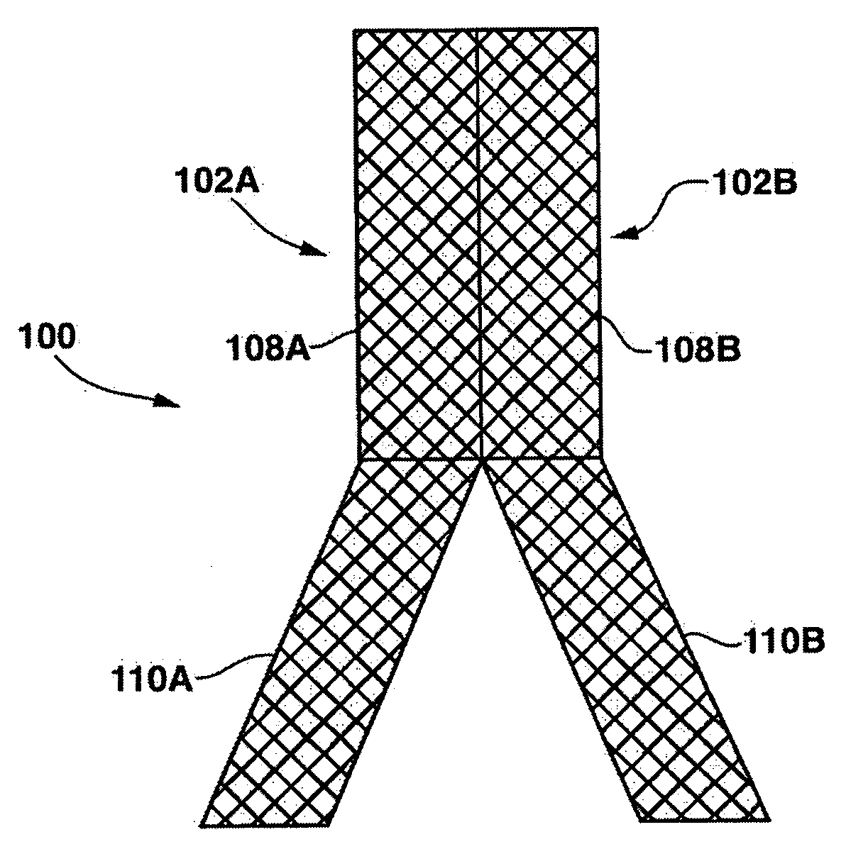
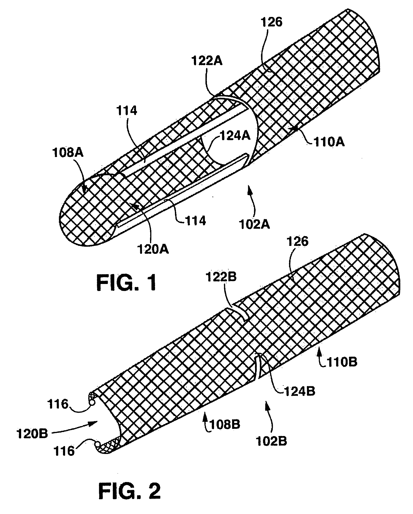
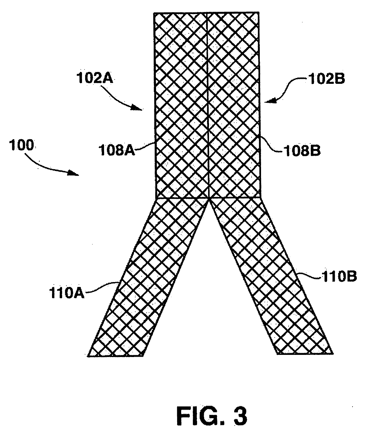
A bifurcation stent system includes a pair of self-expanding stents. Each stent has a C-shaped body section having a generally semicircular cross-section along its length and an O-shaped body section having a circular cross-section along its length. The stents are deployed in vivo such that the edges of the C-shaped body sections abut each other to form a tubular scaffold in a Y-shaped formation that conforms to the bifurcation. In order to connect the stents in vivo, the C-shaped body sections are configured to include a ball and socket connection there between. The C-shaped body sections align and abut to form a tubular scaffold that extends in the main vessel of the bifurcation, while the O-shaped body sections are tubular scaffolds that extend into the respective branch legs of the bifurcation.

Description

FIELD OF THE INVENTION[0001]The invention relates generally endoluminal prostheses, and more particularly to a stent system intended for placement in a bifurcated vessel of a patient.BACKGROUND OF THE INVENTION[0002]A wide range of medical treatments are known that utilize “endoluminal prostheses.” As used herein, endoluminal prostheses are intended to mean medical devices that are adapted for temporary or permanent implantation within a body lumen, including both naturally occurring and artificially made lumens. Examples of lumens in which endoluminal prostheses may be implanted include, without limitation: arteries, such as those located within the coronary, mesentery, peripheral, or cerebral vasculature; veins; gastrointestinal tract; biliary tract; urethra; trachea; hepatic shunts; and fallopian tubes.[0003]Various types of endoluminal prostheses are also known, each providing a component for modifying the mechanics of the targeted luminal wall. For example, stent prostheses are...

Claims


Application Information

Patent Timeline
IPC IPC(8): A61F2/06
CPCA61F2/07A61F2230/0013A61F2002/067A61F2230/006A61F2230/0069A61F2002/065A61F2/06A61F2002/821A61F2/954A61F2/856
Inventor XUE, YUEQIANG
Owner MEDTRONIC VASCULAR INC
Learn More