Method and apparatus for freeze-thaw well stimulation using orificed refrigeration tubing

a technology of orificed refrigeration tubing and well stimulation, which is applied in the field of methods to achieve the effect of facilitating the use of the same diffuser pipe and promoting uniform refrigerant effectiveness

Inactive Publication Date: 2010-10-21
POLAR WELL STIMULATIONS LTD
View PDF11 Cites 21 Cited by
  • Summary
  • Abstract
  • Description
  • Claims
  • Application Information

AI Technical Summary

Benefits of technology

[0021]The present invention makes it possible to freeze a much longer length of wellbore without repositioning the refrigerant tubing assembly as in U.S. patent application Ser. No. 11 / 746,470. In accordance with the present invention, the downhole end of the refrigerant supply tubing may be capped, rather than having expander means as in U.S. patent application Ser. No. 11 / 746,470. The refrigerant supply tubing has multiple orifices along a selected portion of its length. These orifices serve the same function as the “expander means” in U.S. patent application Ser. No. 11 / 746,470, creating the pressure drop necessary to initiate the refrigeration cycle. Accordingly, adjacent formation freezing can be induced along the full length of orificed section of the supply tubing. For purposes of this patent specification, refrigerant supply tubing having orifices as described above may be alternatively referred to as a “diffuser pipe”.
[0022]The configuration, size, and arrangement of the orifices can be varied along the length of the diffuser pipe, using known engineering principles, to suit the requirements of a particular well. For example, it may be desirable to vary these design parameters to allow for pressure drop within the diffuser pipe, to promote uniform refrigerant effectiveness along the length of the diffuser pipe.
[0023]To facilitate use of the same diffuser pipe in different wells having different requirements, a preferred embodiment of the apparatus of the present invention provides for a diffuser pipe with more orifices than might be necessary or optimally effective for use with any particular well. A helical “orifice-isolation wrap”, with multiple internally-projecting dimples or buttons may be disposed around the diffuser pipe, with the dimples or buttons fitting into and effectively plugging selected orifices that are not wanted or needed for a particular well stimulation operation, leaving other orifices open as required. In accordance with this concept, it is possible to design diffuser pipes with particular orifice arrangements that will accommodate two or more different isolation wraps, with each different wrap plugging different patterns of orifices.

Problems solved by technology

The continuous flow of refrigerant through this assembly results in freezing of aqueous fluid in a zone adjacent the expander means and resultant freezing of an adjacent region of the subsurface formation.

Method used


Image

  • Method and apparatus for freeze-thaw well stimulation using orificed refrigeration tubing
  • Method and apparatus for freeze-thaw well stimulation using orificed refrigeration tubing
  • Method and apparatus for freeze-thaw well stimulation using orificed refrigeration tubing

Examples


Embodiment Construction

Review of Prior Art: U.S. Patent Application Ser. No. 11 / 746,470

[0047]The present invention can be best understood after familiarization with the teachings of U.S. patent application Ser. No. 11 / 746,470, as set out in detail in the following paragraphs.

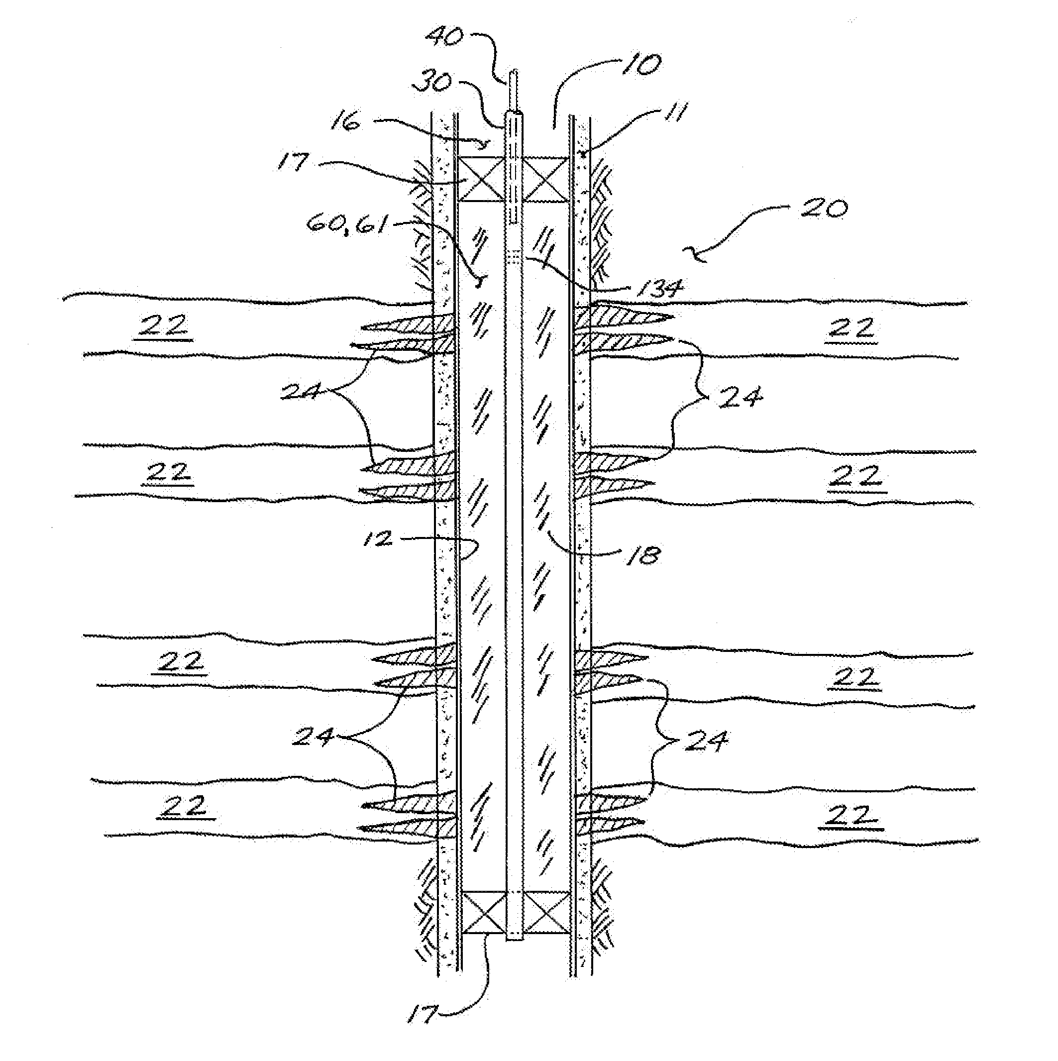
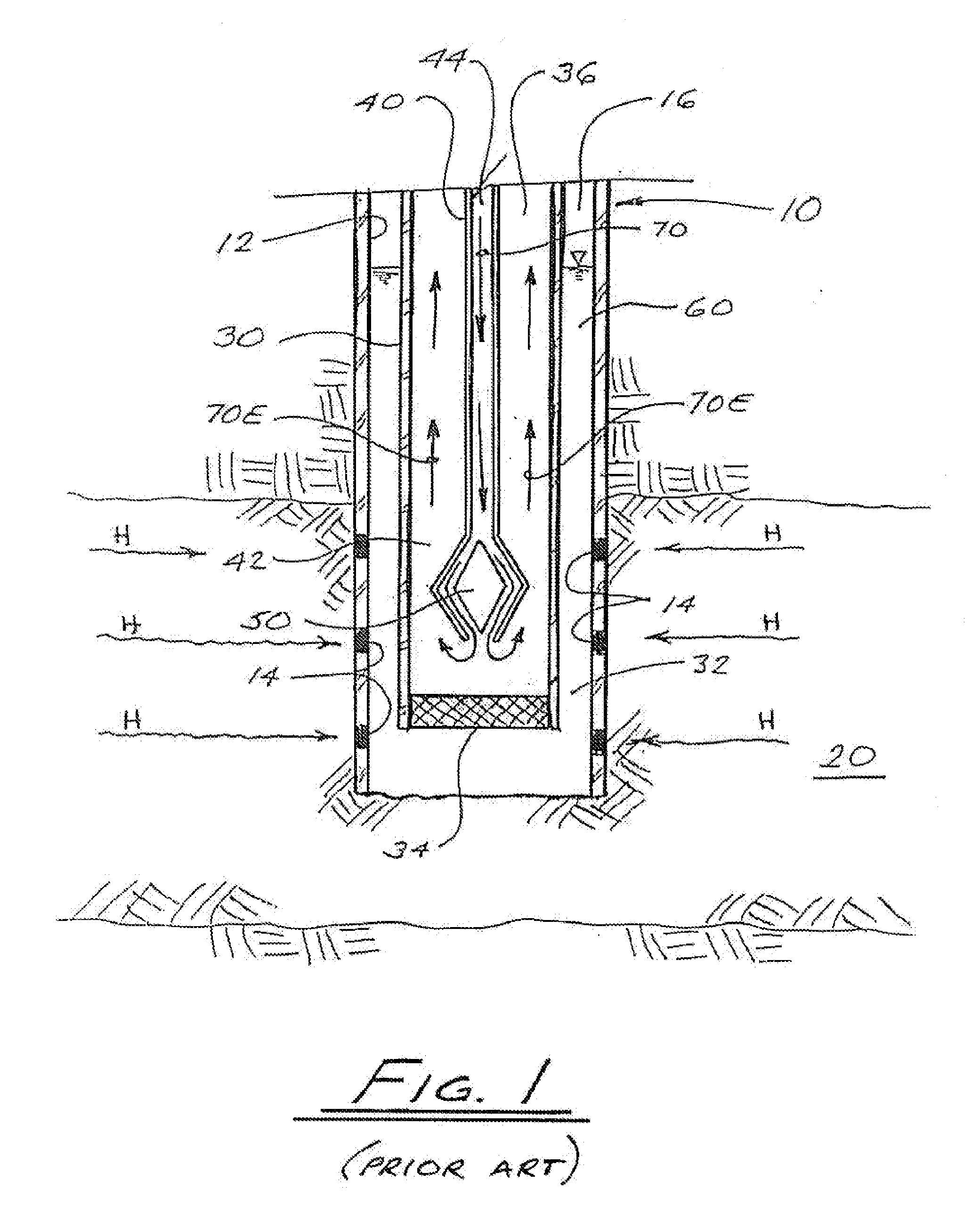
[0048]One embodiment of the method of the U.S. patent application Ser. No. 11 / 746,470 is schematically illustrated in FIG. 1, which shows a vertical well 10 drilled into a hydrocarbon-bearing subsurface formation 20. Well 10 will typically have a well liner 12, with perforations 14 in the production zone (i.e., the portion of well 10 that penetrates formation 20) to allow hydrocarbons H to flow from formation 20 into well 10. In some geologic formations it may be feasible for well 10 to be unlined, such that hydrocarbons can flow directly into well 10. In either case, well 10 can be said to be exposed to formation 20. When well 10 is producing, formation fluids comprising liquid and / or gaseous hydrocarbons are conveyed from the wellbo...


PUM


Abstract

A method and apparatus for introducing refrigerant into a wellbore, for freeze-fracturing a selected region of a subsurface formation, uses refrigerant diffuser pipe having multiple orifices in a selected pattern along a designated section of its length. The orificed supply tubing is disposed within a refrigerant return conduit, thereby forming a tubing annulus. A flow of liquid refrigerant is introduced into the diffuser pipe and flows through the orifices into the tubing annulus, with the orifices acting as expander means creating a pressure drop and causing vaporization of the refrigerant as it passes into the annulus. To facilitate use of the same diffuser pipe in different wells having different requirements, a helical orifice-isolation wrap may be disposed around the diffuser pipe, with the orifice-isolation wrap having orifice-plugging elements arrayed to effectively block fluid flow through selected orifices, while leaving other orifices open as required. In this way, it is possible to design diffuser pipes with particular orifice arrangements that will accommodate two or more different isolation wraps, with each different wrap plugging different patterns of orifices.

Description

CROSS-REFERENCE TO RELATED APPLICATIONS[0001]This application claims the benefit, pursuant to 35 U.S.C. 119(e), of U.S. Provisional Application No. 61 / 170,288, filed on Apr. 17, 2009, and said provisional application is incorporated herein by reference in its entirety for continuity of disclosure.FIELD OF THE INVENTION[0002]The present invention relates in general to methods for enhancing the efficiency of recovery of liquid and gaseous hydrocarbons from oil and gas wells. In particular, the invention relates to methods for fracturing a subsurface formation to facilitate or improve the flow of hydrocarbon fluids from the formation into a well.BACKGROUND OF THE INVENTION[0003]A well drilled into a hydrocarbon-bearing subsurface formation, during an initial post-completion stage, commonly produces crude oil and / or natural gas without artificial stimulation, because pre-existing formation pressure is effective to force the crude oil and / or natural gas out of the formation into the well...

Claims


Application Information

Patent Timeline
Patent Type & Authority Applications(United States)
IPC IPC(8): E21B43/26E21B43/24
CPCE21B36/001E21B36/00E21B43/26E21B43/2605
Inventor KOSAKEWICH, DARRELL S.
Owner POLAR WELL STIMULATIONS LTD
Why Eureka
Try Eureka