Flexible under-frame shield

a shield and flexible technology, applied in the field of crop shields, can solve the problems of insufficient shielding, insufficient shielding for providing continuous, and many previously available shielding arrangements failing to provide adequate access to the lower portion of the vehicle, and achieve the effect of reducing friction and wear

Active Publication Date: 2010-10-21
DEERE & CO
View PDF11 Cites 27 Cited by
  • Summary
  • Abstract
  • Description
  • Claims
  • Application Information

AI Technical Summary

Benefits of technology

[0004]An under-frame shields utilizes a combination of solid and flexible material with attachment and fastening structure facilitating axle movement and the resulting changes in position between attachment locations. A tarp or rubber material or other flexible material under the steering or tie rod mechanism accommodates twisting of the axle and, in a system with axle supporting rods, provides protection under substantially all the axle and axle supports. One end of the flexible shield portion attaches directly to the axle and moves with the axle. The opposite end of the flexible material is supported by brackets depending from the frame. A resilient strap system connects the opposite end to a generally rigid shield portion. An ultra-high molecular weight material (UHMW) bearing surface is interposed between the end of the flexible material and the rigid shield portion. In one embodiment, the rigid shield portion includes an upwardly opening sheet metal channel extending under the central belly portion of the vehicle. The strap system and contact surface allow the shield to move fore-and-aft with relatively little friction and wear while maintaining a consistent tension on the flexible shield material for maximum under-frame clearance and protection.

Problems solved by technology

With movement of the axle, the distance between the axle and fixed locations on the under-frame will vary so that stationary arrangements are ineffective.
Such shields are not entirely satisfactory for providing a continuous barrier between the plants and the vehicle that does not harm the crop while adequately protecting the vehicle when operating in either the forward or reverse direction.
In addition, many previously available shielding arrangements fail to provide adequate access to the lower portion of the vehicle during inspection and maintenance.

Method used


Image

  • Flexible under-frame shield
  • Flexible under-frame shield
  • Flexible under-frame shield

Examples


Embodiment Construction

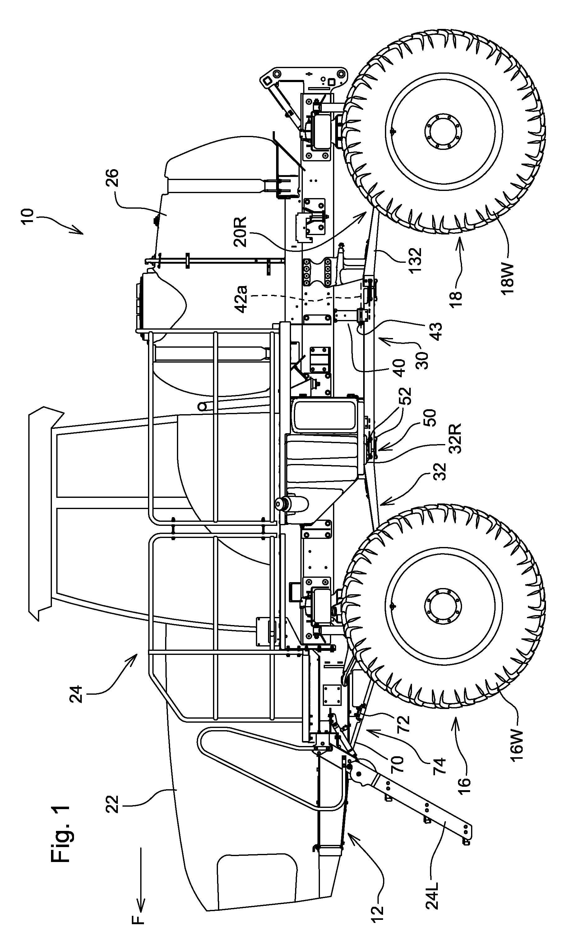
[0013]Referring to FIG. 1 therein is shown an agricultural vehicle 10 adapted for movement over a field of tall plants. As shown, the vehicle 10 is self-propelled sprayer having a main frame 12 supported for forward movement over the ground by a forward wheel axle assembly 16 and an aft wheel axle assembly or structure 18 including transverse beams 16b and 18b supporting transversely spaced wheels 16w and 18w, respectively. At least the forward axle assembly 16 is steerable and is movably connected to the main frame 12 by suspension structure 20F (FIG. 5) which allows the beam 16b to rock vertically as the wheels 16w move over ground surface irregularities. A cushioning member or air bag 16c is interposed between the frame 12 and each side of the beam 16b, and shock absorbers 16s help dampen axle movement. As shown, the suspension structure 20F is of the type shown and described in the aforementioned U.S. application Ser. No. 12 / 045,107 and includes pairs of connecting rods 20c whic...


PUM


Abstract

An under-frame shield, particularly useful with crop sprayers and other implements which traverse fields of plants, includes one or more flexible sheet material shields connected to axle structure and to a central rigid shield by resilient connectors to facilitate suspension system movement in all directions without sacrificing ground clearance. The connection structure and sheet material shields maintain a smooth, seamless protective surface on the under side of the machine to reduce vehicle and crop damage.

Description

FIELD OF THE INVENTION[0001]The present invention relates to crop shields for agricultural vehicles and, more specifically, to a flexible under-frame shield for such vehicles.BACKGROUND OF THE INVENTION[0002]Agricultural vehicles such as self-propelled sprayers have undersides that must be shielded to protect the vehicle from wear and damage by the plants and to protect the plants contacting the vehicle, particularly when the vehicle moves through tall crops. Currently available under-frame shielding typically utilizes stationary sheet metal which cannot flex to allow axle movements in floating axle or pivoting axle suspension systems. With movement of the axle, the distance between the axle and fixed locations on the under-frame will vary so that stationary arrangements are ineffective. Various shielding configurations have been proposed, such as shown in commonly assigned U.S. Pat. Nos. 5,405,292; 5,850,727; and 7,025,168. Such shields are not entirely satisfactory for providing a...

Claims


Application Information

Patent Timeline
Patent Type & Authority Applications(United States)
IPC IPC(8): B62D21/00B62D21/18B60R99/00
CPCA01D75/18A01B71/08
Inventor FAUSCH, JOSHUA JUELCARLSON, BRANDON C.BUSE, SCOTT M.BAXTER, GARRY E.
Owner DEERE & CO
Why Eureka
Try Eureka