This helps you quickly interpret patents by identifying the three key elements:
Problems solved by technology
Method used
Benefits of technology
Benefits of technology
[0004]It is therefore an object of the present invention to eliminate the aforementioned conventional problems and to provide a mixing and degassing apparatus capable of mixing and degassing a material to be treated even if a container revolving around a rotational axis does not rotate on its own axis, of increasing the amount of the material which can be treated at a time, and of increasing the number of revolution of the revolving container.
[0010]In this mixing and degassing apparatus, the material can be mixed by applying the shearing stress to the material by means of the shearing stress applying portion even if the material in the container is adhered to the inner wall of the container by centrifugal force. That is, since the container revolves around the rotation axis of the rotating base in accordance with the rotation of the rotating base, centrifugal force is applied to the material, which is contained in the container, in such a direction that the material falls away from the rotation axis of the rotating base, so that the material is intended to be collected in the region (the maximum centrifugal force applying region), which is farthest from the axis of revolution (the rotation axis of the rotating base), on the inner wall of the container. However, since the shearing stress applying portion is arranged in the vicinity of the maximum centrifugal force applying region on the inner wall of the container, it is possible to prevent the material collected in the maximum centrifugal force applying region from remaining therein, so that it is possible to fluidize the material in the container.
[0011]It is possible to apply a great shearing stress to the material existing between the shearing stress applying portion and the maximum centrifugal force applying region by arranging the shearing stress applying portion in the vicinity of the maximum centrifugal force applying region, so that it is possible to precisely treat the material. That is, the traveling velocity of the material existing between the shearing stress applying portion and the maximum centrifugal force applying region is higher as the material is located nearer to the shearing stress applying portion. In addition, the variation in velocity (velocity gradient) of the material between the shearing stress applying portion and the inner wall surface of the container is greater as the distance between the shearing stress applying portion and the inner wall surface of the container is smaller. Therefore, if the shearing stress applying portion is arranged in the vicinity of the inner wall surface of the container, it is possible to cause a great velocity gradient to the material existing between the shearing stress applying portion and the inner wall surface of the container to mix the material, and it is possible to apply stress (shearing stress, shearing force) to the material. In addition, if stress is applied to the material, it is possible to precisely mix the material, and it is possible to decrease the size of particles contained in the material. Moreover, if the shearing stress applying portion is arranged in the vicinity of the maximum centrifugal force applying region, it is possible to surely cause the shearing stress applying portion to contact the material even if the amount of the material is small, and it is possible to increase the contact area of the shearing stress applying portion, so that it is possible to precisely mix the material.
[0015]In this mixing and degassing apparatus, when the rotating base is rotated on the first rotation axis by the first rotating mechanism, the shearing stress applying portion of the shearing stress applying member is rotated on the second rotation axis by the rotation of the rotating base, so that it is possible to apply a shearing stress to the material in the container to mix the material.
[0017]In this mixing and degassing apparatus, it is possible to precisely mix the material since it is possible to increase the region in which the shearing stress is applied by the plurality of shearing stress applying portions.
Problems solved by technology
However, if a mixing and degassing apparatus has members (a container and a rotating shaft) rotating on their own axes while moving along the trajectory of revolution thereof as conventional mixing and degassing apparatuses, the rotating members are greatly influenced by acceleration, so that the rotating mechanism thereof is not easily designed.
In addition, if such an influence of acceleration is considered, it is not possible to increase the weight and volume of the container, so that there is a limit to the amount of the material capable of being treated at a time.
Method used
Image
Click on the blue label to locate the original text in one second.
Reading with bidirectional positioning of images and text.
Examples
first preferred embodiment
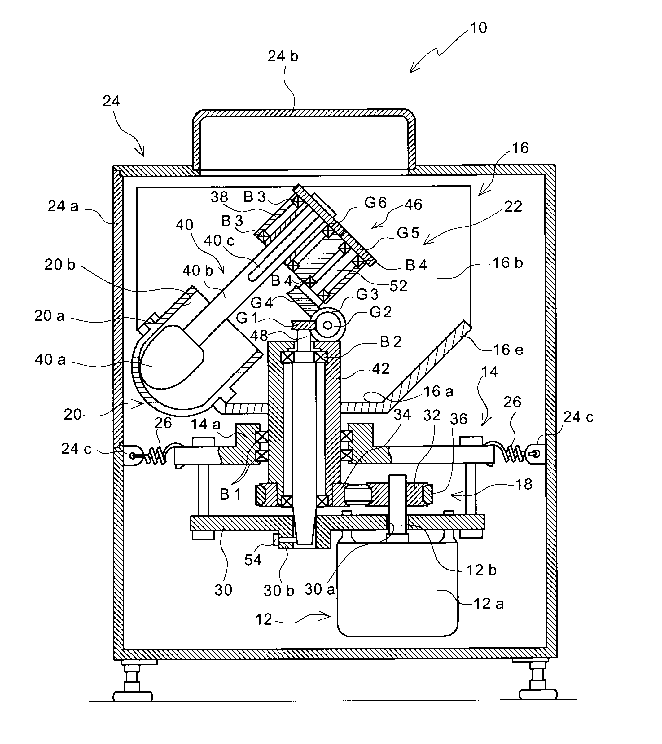
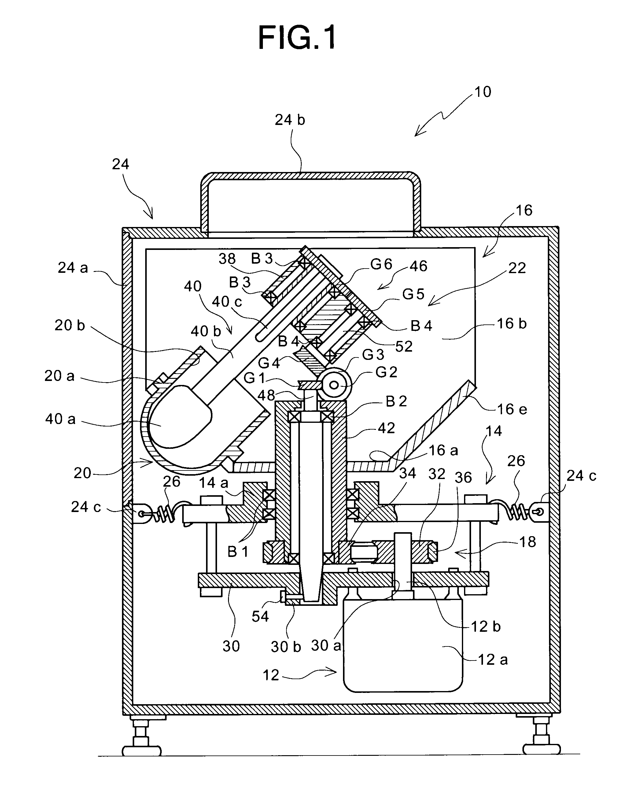
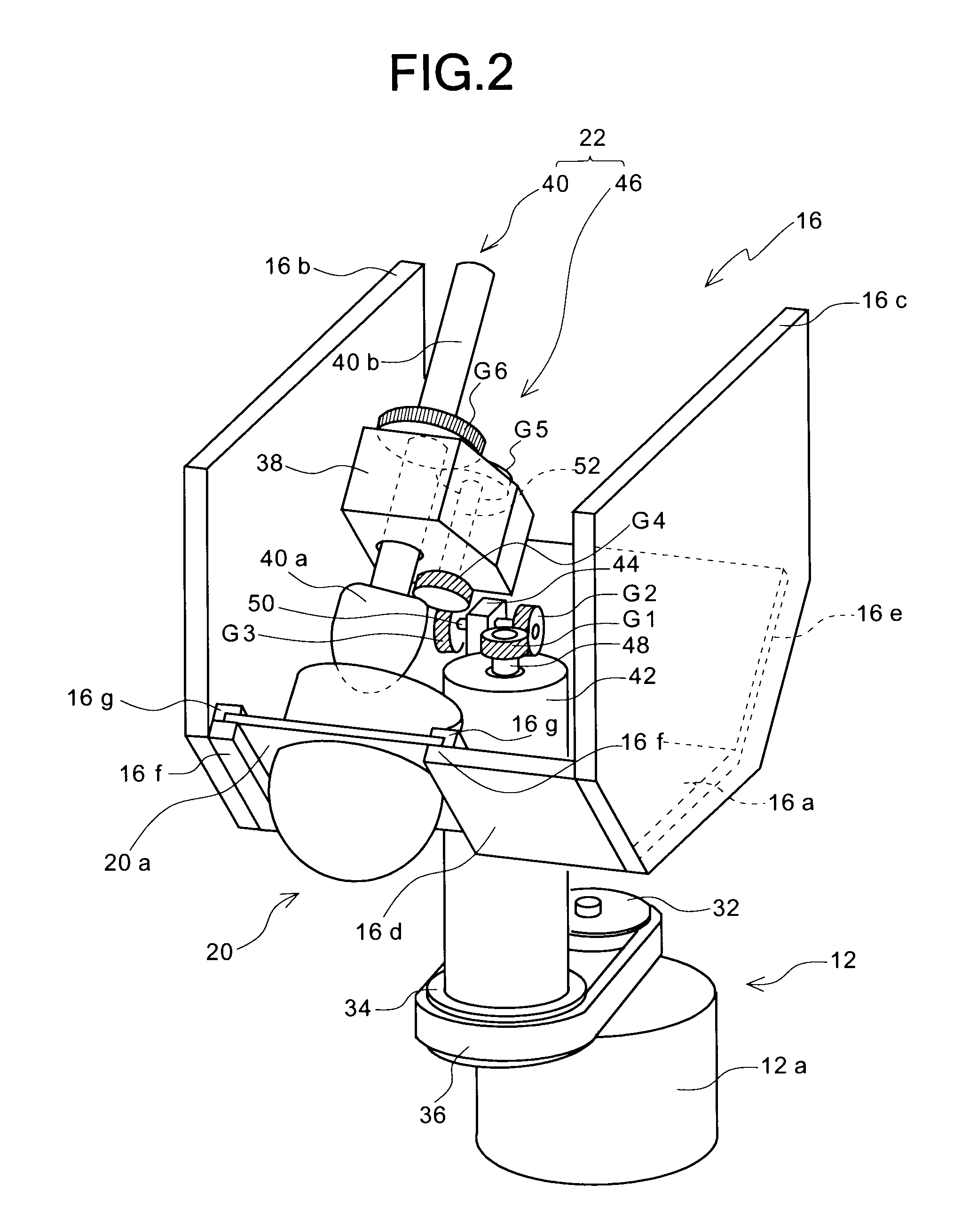
[0035]FIGS. 1 through 3 show the first preferred embodiment of a mixing and degassing apparatus according to the present invention. The mixing and degassing apparatus in this preferred embodiment is an apparatus for mixing a material to be treated while releasing bubbles from the material to the outside (while degassing the material). As materials to be treated by the apparatus, there are various materials, such as soldering pastes, impression materials for dental, greases, resins, pigments, various powders, and composite materials (epoxy resins, phenol resins), e.g., carbon composites used for bodies of airplanes and vehicles.
[0036]As shown in FIGS. 1 through 3, the mixing and degassing apparatus 10 in this preferred embodiment comprises: a supporting member 14 on which a motor 12 is mounted; a rotating base 16 which is rotatably supported on the supporting member 14; a first rotating mechanism 18 for rotating the rotating base 16 by means of the motor 12; a container 20 which is f...
second preferred embodiment
[0087]FIGS. 10A and 10B schematically show part of the second preferred embodiment of a mixing and degassing apparatus according to the present invention. In this preferred embodiment, a cylindrical container 320 having a bottom is used in place of the container 20, and a pair of shearing stress applying members (first and second shearing stress applying members) 340, 340 are used in place of the shearing stress applying member 40. In addition, a pair of motors 346, 346 are used in place of the second rotating mechanism 46, and a second shaft supporting portion 338 is used in place of the second shaft supporting portion 38 of the rotating base 16. Other constructions are the same as those in the above-described preferred embodiment, so that repeated descriptions thereof are omitted.
[0088]The container 320 is fixed to the peripheral portion of the rotating base 16 so that the central axis thereof (the central axis of the cylindrical container 320, which is an axis extending from the ...
third preferred embodiment
[0107]FIG. 15 schematically shows part of the third preferred embodiment of a mixing and degassing apparatus according to the present invention. In this preferred embodiment, a plurality of shearing stress applying members 540, each of which has a shearing stress applying portion 540a, are provided in place of the pair of shearing stress applying member (the first and second shearing stress applying members) 340 and 340. Other constructions are substantially the same as those in the above-described second preferred embodiment, so that repeated descriptions thereof are omitted.
[0108]The plurality of shearing stress applying portions 540a are arranged on a circumference which is concentric with the inner wall surface of the container 320. In addition, the apparatus is provided with a rotating mechanism (not shown) for rotating the plurality of shearing stress applying members 540. As shown in FIG. 15, the shearing stress applying portions 540a are designed to rotate in such directions...
PUM
Property
Measurement
Unit
Stress optical coefficient
aaaaa
aaaaa
Abstract
A mixing and degassing apparatus includes: a supporting member 14; a rotating base 16 supported on the supporting member so as to be rotatable on a first rotational axis Y1; a first rotating mechanism 18 for rotating the rotating base on the first rotational axis; a container 20 which is fixed to a peripheral portion of the rotating base and which is rotatable with the rotating base around the first rotational axis; a shearing stress applying member 40 having a shearing stress applying portion 40a which is arranged in the vicinity of a maximum centrifugal force applying region on the inner wall surface of the container and which is rotatable on a second rotational axis Y2; and a second rotating mechanism 46 for rotating the shearing stress applying portion of the shearing stress applying member on the second rotational axis to apply a shearing stress to a material to be treated in the container, wherein if the rotating base rotates on its own axis to revolve the container, the shearing stress applying portion rotates on its own axis while moving along the trajectory of revolution of the container, so that a shearing stress is applied to the material in the container to mix and degas the material.
Description
TECHNICAL FIELD[0001]The present invention relates generally to a mixing and degassing apparatus. More specifically, the invention relates to a mixing and degassing apparatus for mixing a material to be treated while releasing bubbles from the material (while degassing the material).BACKGROUND ART[0002]As a conventional mixing and degassing apparatus, there is known a mixing and degassing apparatus for mixing and degassing a material to be treated by rotating a container holder, which holds a container for containing therein a material to be treated, on its own axis while revolving the container holder so as to move along the trajectory of revolution thereof (see, e.g., Japanese Patent Laid-Open No. 10-43568). In this mixing and degassing apparatus, the container holder is rotatably supported on the peripheral portion of a rotator. The rotator is designed to be rotated for revolving the container holder around the rotation axis thereof while the container holder is rotated on its ow...
Claims
Application Information
Patent Timeline
Application Date:The date an application was filed.
Publication Date:The date a patent or application was officially published.
First Publication Date:The earliest publication date of a patent with the same application number.
Issue Date:Publication date of the patent grant document.
PCT Entry Date:The Entry date of PCT National Phase.
Estimated Expiry Date:The statutory expiry date of a patent right according to the Patent Law, and it is the longest term of protection that the patent right can achieve without the termination of the patent right due to other reasons(Term extension factor has been taken into account ).
Invalid Date:Actual expiry date is based on effective date or publication date of legal transaction data of invalid patent.

