Automatic electrode control system
An automatic control and electrode technology, which is applied to electrical components, electric heating devices, heating through discharge, etc., can solve the problems that the diameter of the electrode circle cannot be adjusted, it is easy to shake during use, and the resistance between electrodes can be reduced.
- Summary
- Abstract
- Description
- Claims
- Application Information
AI Technical Summary
Problems solved by technology
Method used
Image
Examples
Embodiment 1
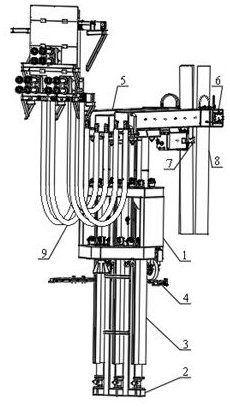
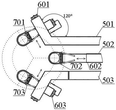
[0051] Such as Figure 1 to Figure 4 As shown, the electrode automation control system includes a mobile pedestal 1, a base 2, a lifting device 3, a station adjustment device 4, a cross arm 5, an electrode circle adjustment device 6 and an electrode clamping device 7. In this embodiment, the mobile The base frame 1 is used as the load-bearing body and is rotatably installed on the base platform through the station adjustment device 4. The base 2 is horizontally arranged on the bottom of the mobile base frame 1. The bottom of the lifting device 3 is fixed on the base 2 horizontally. The lifting device The top of 3 is fixed on the bottom of the cross arm 5, the lifting device 3 is used to drive the cross arm 5 to lift, and the station adjustment device 4 is used to drive the mobile base frame 1, the base 2, the lifting device 3 and the cross arm 5 to rotate as a whole.
[0052] Specifically, the transverse arm 5 is divided into a first transverse arm 501, a second transverse arm...
Embodiment 2
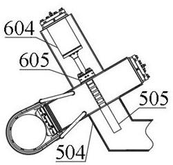
[0056] Such as Figure 4 with Figure 5 As shown, the electrode clamping device 7 includes a clamping housing 704, an arc-shaped clamping seat 705, a moving clamp 706, a conductive wire 707, a moving groove 708, a transmission plate 709, a clamping connector 710, a clamping cylinder 711 and Roller row 712, in this embodiment, the end of the clamping shell 704 of the electrode clamping device 7 is provided with an arc-shaped clamping seat 705 and a moving clamp 706, and the arc-shaped clamping seat 705 and the moving clamp 706 are used for cooperation On the fixed electrode 8, the outer wall of the movable clamp 706 is in contact with the conductive wire 707, and the two ends of the movable clamp 706 are arranged on the transmission plate 709. 710 is connected to the clamping oil cylinder 711 , and two sets of roller rows 712 are respectively arranged on the upper and lower surfaces of the clamping housing 704 , and cooperate with the chute 505 on the inner wall of the cross a...
Embodiment 3
[0058] Such as Image 6 with Figure 7 As shown, the mobile base frame 1 is rotatably installed on the foundation platform as a load-bearing body. The base platform is a cement structure or a frame base. The load-bearing plate on the mobile base frame 1 is provided with three upper through holes 101, and the surroundings of the upper through holes 101 are symmetrical. A plurality of upper guide wheels 102 are provided, and three lower through holes 103 are correspondingly opened on the lower bearing plate of the mobile base frame 1 , and a plurality of lower guide wheels 104 are arranged symmetrically around the lower through holes 103 . Specifically, the upper through hole 101 and the lower through hole 103 are correspondingly provided for vertically installing the lifting sleeve 304, and each through hole is configured with four to eight guide wheels, and the guide wheels are arranged symmetrically and are used to guide the lifting sleeve 304 vertically. Straight moving, go...
PUM
 Abstract
Description
Claims
Application Information
 - R&D
- Intellectual Property
- Life Sciences
- Materials
- Tech Scout
- Unparalleled Data Quality
- Higher Quality Content
- 60% Fewer Hallucinations
Browse by: Latest US Patents, China's latest patents, Technical Efficacy Thesaurus, Application Domain, Technology Topic, Popular Technical Reports.
© 2025 PatSnap. All rights reserved.Legal|Privacy policy|Modern Slavery Act Transparency Statement|Sitemap|About US| Contact US: help@patsnap.com


