
System and method for performing image correction

Active Publication Date: 2010-10-21
NVIDIA CORP
View PDF99 Cites 34 Cited by
  • Summary
  • Abstract
  • Description
  • Claims
  • Application Information

AI Technical Summary

Benefits of technology

[0006]Accordingly, what is needed is a system and method for correcting image data in an efficient manner. Embodiments provide for separably processing portions (e.g., patches) of an image based on spline surfaces (e.g., a Bezier surface) to correct for b distortions, e.g., from vignetting. The use of spline surfaces facilitates efficient hardware implementations (e.g., via linear interpolators) and provides an intuitive and computationally stable selection. Embodiments further correct pixels as the pixels are received from the sensor for a variety of effects including lens shading effects (vignetting), optical crosstalk, and electrical crosstalk. Moreover, the image correction may be performed on a per channel and illumination type basis.

Problems solved by technology

As technology has advanced, cameras have advanced accordingly but still face certain persistent issues.
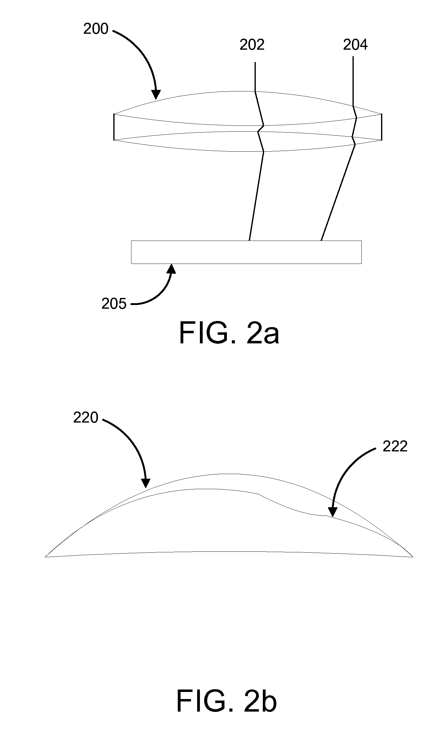
This bending of light results in inconsistent brightness across the sensor such that areas in the middle are much brighter than areas on the edges.
Further, light may get stuck or not pass through as a result of interacting with the lens housing.
Thus, light coming through a lens system and forming an image on a film plane (digital sensor or film) will be unevenly attenuated across the image plane and color spectrum due to imperfections in the lens and due to the angle of the light as it strikes image forming medium (film or digital array of sensors) in particular the color filter array which filters the light and guides it into the image forming device.
However, high order polynomials are computationally expensive and are complicated to execute on hardware of fixed precision.
Further, higher order polynomials are numerically unstable as small variations can result in large changes in the polynomial.
All these characteristics make polynomial representation not a viable solution for the lens shading problem in terms of being computationally intensive and not intuitive.

Method used


Image

  • System and method for performing image correction
  • System and method for performing image correction
  • System and method for performing image correction

Examples


Embodiment Construction

[0021]Reference will now be made in detail to the preferred embodiments of the present invention, examples of which are illustrated in the accompanying drawings. While the invention will be described in conjunction with the preferred embodiments, it will be understood that they are not intended to limit the invention to these embodiments. On the contrary, the invention is intended to cover alternatives, modifications and equivalents, which may be included within the spirit and scope of the invention as defined by the appended claims. Furthermore, in the following detailed description of embodiments of the present invention, numerous specific details are set forth in order to provide a thorough understanding of the present invention. However, it will be recognized by one of ordinary skill in the art that the present invention may be practiced without these specific details. In other instances, well-known methods, procedures, components, and circuits have not been described in detail ...


PUM


Abstract

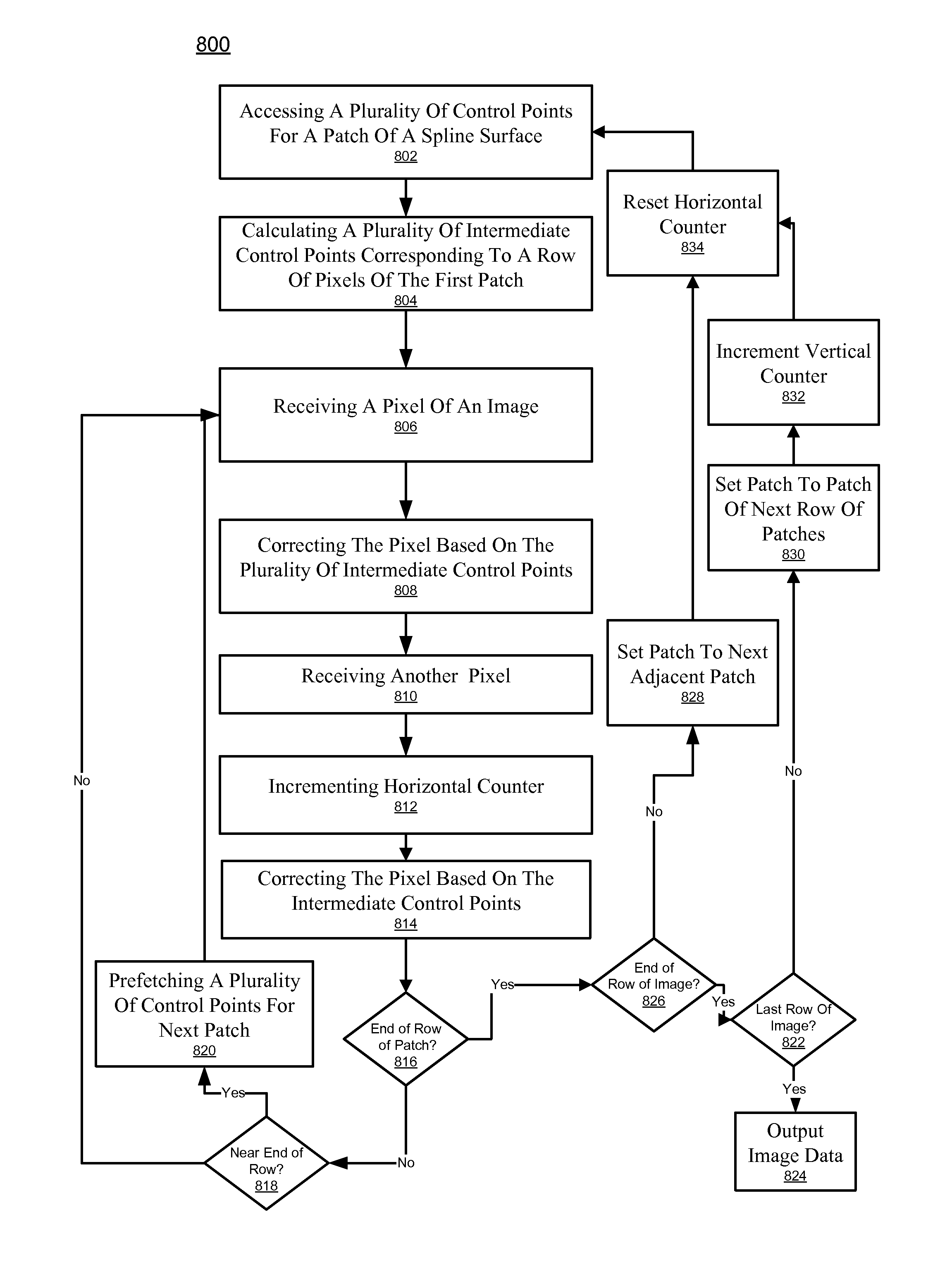
A system and method for correcting image data. Embodiments of the present invention provide image correction to overcome various lens effects, optical crosstalk, and electrical crosstalk. In one embodiment, the method includes accessing, within an electronic system, a plurality of control points for a patch of a spline surface and calculating a plurality of intermediate control points corresponding to a row of pixels of the patch. The method further includes receiving a pixel of an image and correcting the pixel based on the plurality of intermediate control points in streaming scanline column-wise or row-wise order.

Description

RELATED U.S. APPLICATIONS[0001]This application claims the benefit of and priority to the copending provisional patent application Ser. No. 61 / 170,014, Attorney Docket Number NVID-P003817-US0, entitled “SYSTEM AND METHOD FOR IMAGE CORRECTION,” with filing date Apr. 16, 2009, and hereby incorporated by reference in its entirety.[0002]This application is related to copending non-provisional patent application, Ser. No. ______, Attorney Docket Number NVID-P003817-US1, entitled “SYSTEM AND METHOD FOR IMAGE CORRECTION,” with filing date ______, and hereby incorporated by reference in its entirety.FIELD OF THE INVENTION[0003]Embodiments of the present invention are generally related to digital image signal processing.BACKGROUND OF THE INVENTION[0004]As technology has advanced, cameras have advanced accordingly but still face certain persistent issues. Particularly, as light passes through a camera lens, the light is bent as the light refracts. This bending of light results in inconsistent...

Claims


Application Information

Patent Timeline
IPC IPC(8): G06K9/40
CPCH04N5/3572H04N17/00G06T17/30H04N25/61
Inventor CABRAL, BRIANHE, HUING, ELENATAKEMOTO, SOHEI
Owner NVIDIA CORP
Learn More