
Fast VCO calibration for frequency synthesizers

a frequency synthesizer and voltage control technology, applied in the field of frequency synthesizers, can solve the problems of poor phase noise of the pll, achieve the effects of improving the phase noise performance of the pll, shortening the settling time of the frequency synthesizer, and minimizing the vco gain

Inactive Publication Date: 2005-02-22
PROCOMM
View PDF3 Cites 19 Cited by
  • Summary
  • Abstract
  • Description
  • Claims
  • Application Information

AI Technical Summary

Benefits of technology

An object of this invention is to minimize the VCO gain without scarifying the tolerance of process and temperature variation of the VCO. Another object of the invention is to improve the phase noise performance of the PLL. Still another of this invention is to shorten the settling time of a frequency synthesizer. These objects are achieved by first calibrating the VCO to within a small tolerance of the desired VCO control voltage. The VCO frequency is incremented or decremented according the to frequency measurement result. When the VCO frequency error is large during calibration, the control word is changed in discrete steps to bring the frequency of the VCO to within a preset tolerance. When the VCO frequency is close to the desired frequency, the PLL is switched to a conventional analog operating mode to accurately lock the VCO frequency with the reference frequency. This results in a shorter search time than prior art, and allows calibration during channel switching. This not only achieves more accurate results than prior art, but also potentially supports frequency hopping in the RF wireless communications. It also eliminates the need for a look-up table to store the calibration results for all the RF channels, which results in a more efficient hardware implementation

Problems solved by technology

Unfortunately, this leads to a large VCO gain (Kvco), which results in poor phase noise of the PLL.

Method used


Image

  • Fast VCO calibration for frequency synthesizers
  • Fast VCO calibration for frequency synthesizers
  • Fast VCO calibration for frequency synthesizers

Examples


Embodiment Construction

The synthesizer of the present invention operates with two sequential modes; a calibration mode and an analog mode. During the calibration mode, the synthesizer locks the frequency of a VCO coarsely but rapidly to the reference frequency using a first phase-locked loop by generating an approximate control voltage for the VCO and to set the VCO frequency within a certain tolerance. This approximate control voltage is used to start operating a conventional phase-locked loop in the analog mode for fine tuning of the VCO.

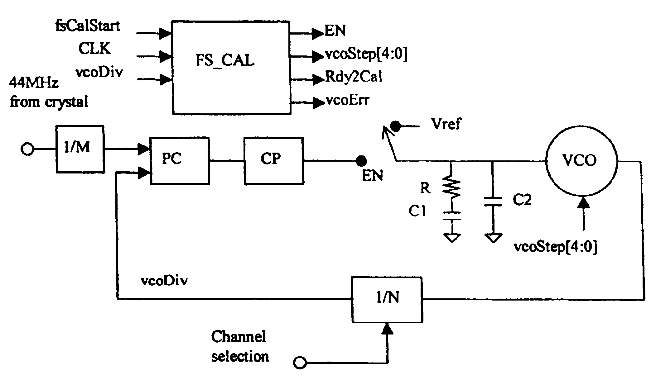
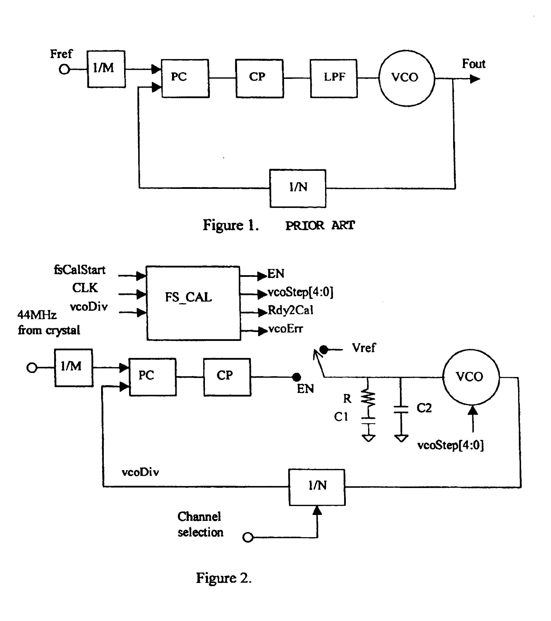
The calibration circuit with the PLL is drawn in FIG. 2. The calibration PLL uses a FS_CAL block as a coarse phase detector instead of the conventional PC+CP phase detector shown in FIG. 1. The calibration is triggered by a rising edge of fsCalStart to FS_CAL. It first breaks the conventional PLL loop by raising EN signal to enable FS_CAL. Now the VCO control input is connected to a fixed reference voltage vcoStep[4.0] derived and held from the FS_CAL phase detector. Th...


PUM


Abstract

The voltage-oscillator (VCO) in a frequency synthesizer using a phase-locked loop (PLL) is calibrated during power up or channel switching. The VCO has a coarse frequency control and a fine frequency control. The coarse control consists of digital bits that are used for calibration. The coarse control is connected to the charge pump output as in a regular PLL. By searching for the optimal control setting, the center frequency of the VCO is trimmed close to the desired frequency for the PLL to lock. This allows small VCO gain without losing the tolerance of process and temperature variations. As a result, the PLL phase noise performance is improved.

Description

BACKGROUND OF THE INVENTION1. Field of the InventionThis invention relates to frequency synthesizers, particularly to the voltage-controlled oscillator (VCO) of a frequency synthesizers for radio transceivers.2. Brief Description of Related ArtIn wireless communications system, frequency synthesizers are used to generate stable local oscillator (LO) frequencies with very high accuracy. A frequency synthesizer is usually a phase-locked loop (PLL) whose simplified diagram is shown in FIG. 1. It consists of a reference frequency divider (1 / M), a feedback frequency divider (1 / N), a phase comparator (PC), a charge pump (CP), a loop filter (LPF) and a VCO. Under phase-locked condition, the frequencies of the two signals at the PC inputs are identical. This forces the VCO frequency (Fout) to be NIM of the input reference frequency (Fref).Usually the center frequency of a free-running VCO exhibits large variations over process and temperature. In order to generate the desired LO frequency, ...

Claims


Application Information

Patent Timeline
Patent Type & Authority Patents(United States)
IPC IPC(8): H03B21/00H03L7/113H03L7/187
CPCH03L7/187H03L7/113
Inventor DAI, LIANGHUANG, JIEWANG, KEVIN HSI-HUAIPAI, HUNG-CHUAN
Owner PROCOMM
Learn More