High power laser with chirped pulse amplification

a high-power laser and pulse technology, applied in the direction of laser arrangement, laser details, electrical equipment, etc., can solve the problems of difficult measurement of the contrast of ultra-high intensity pulses, damage or even destruction, etc., and achieve the effect of high peak intensity

Inactive Publication Date: 2017-03-30
UK RES & INNOVATION LTD
View PDF4 Cites 11 Cited by
  • Summary
  • Abstract
  • Description
  • Claims
  • Application Information

AI Technical Summary

Benefits of technology

[0007]The present invention is directed to improvements in pulse stretchers for high power lasers, such as chirped pulse amplification lasers. The pulse stretcher of the present inventions replaces conventional metal coated diffraction gratings with at least one transmission diffraction grating in the stretcher. Preferably, the transmission diffraction grating is used for the second grating if a pair of gratings is used in the stretcher. The result is significantly improved phase noise performance of the output pulse, and therefore a reduction in the noise floor close to the pulse so as to improve contrast pedestal.
[0009]The laser pulse may be a seed laser pulse generated from, for example, a titanium:sapphire laser and acts as a starting pulse for stretching, amplification and compression to increase the power of the pulse. The laser pulse includes a range of wavelengths, which will usually be a continuum or spread of wavelengths. The diffraction grating diffracts the light different amounts according to its wavelength. Accordingly, the wavelengths leaving the diffraction grating are distributed or spread throughout a range of diverging angles from a point or region on the grating. The wavelengths are divergent and / or spatially dispersed from one another in the angular spread. The transfer optics change the direction of the wavelengths of the pulse diverging from the grating such that the different wavelengths are no longer diverging but directed towards each other, that is, they are converging. The different wavelength components do not converge on a point but reach the transmission diffraction grating before they are able to do so. The transfer optics therefore may be considered to perform a focussing function but do not bring the wavelengths to a focus. The transmission diffraction grating may diffract and align the wavelength components of the pulse. After passing through the transmission diffraction grating the path direction of each of the wavelength components of the pulse are aligned parallel, that is they are collimated. The advantage of a transmission diffraction grating is reduced phase noise compared to a conventional metal coated reflective diffraction grating.
[0041]The transmission diffraction grating may be uncoated so that spectral phase noise induced by said transmission diffraction grating is less than that of an equivalent reflective metal coated grating, i.e. one having the same line density, thereby improving the contrast pedestal of the output amplified pulse. The plane surface of the grating, that is the surface without grooves, may have an anti-reflection coating.
[0043]The diffraction gratings of the pulse stretcher are preferably arranged to cause the higher frequency components (shorter wavelength) to travel a longer path than the lower frequency components (longer wavelength). This means the higher frequency components are temporally delayed compared to the lower frequency components. The pulse compressor delays the lower frequency components so as to bring the high and low frequency components more into temporal alignment, that is, temporally coincident, so as to provide high peak intensity.

Problems solved by technology

Clean laser pulses are required to restrict any destructive pre-plasma dynamics, because excessive pre-pulse intensity can significantly modify, damage or even destroy solid targets due to pre-plasma formation prior to the arrival of the main pulse.
Conventionally, the contrast of the ultra-high intensity pulses has been difficult to measure.

Method used


Image

  • High power laser with chirped pulse amplification
  • High power laser with chirped pulse amplification
  • High power laser with chirped pulse amplification

Examples


Embodiment Construction

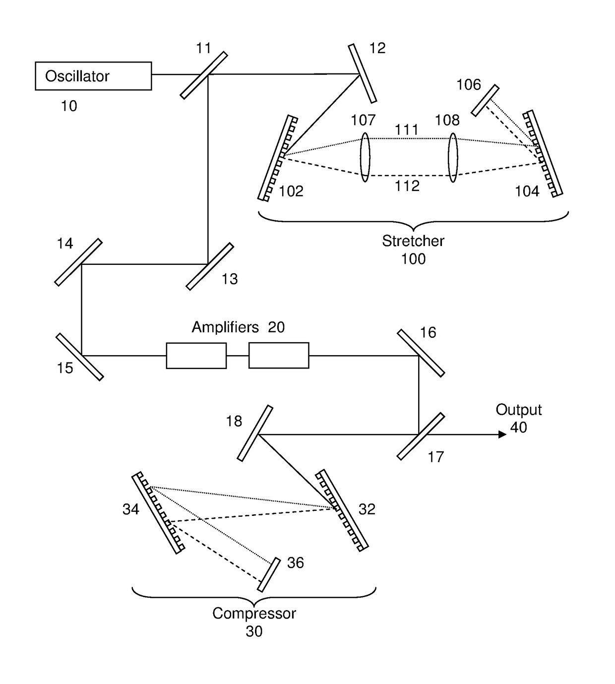
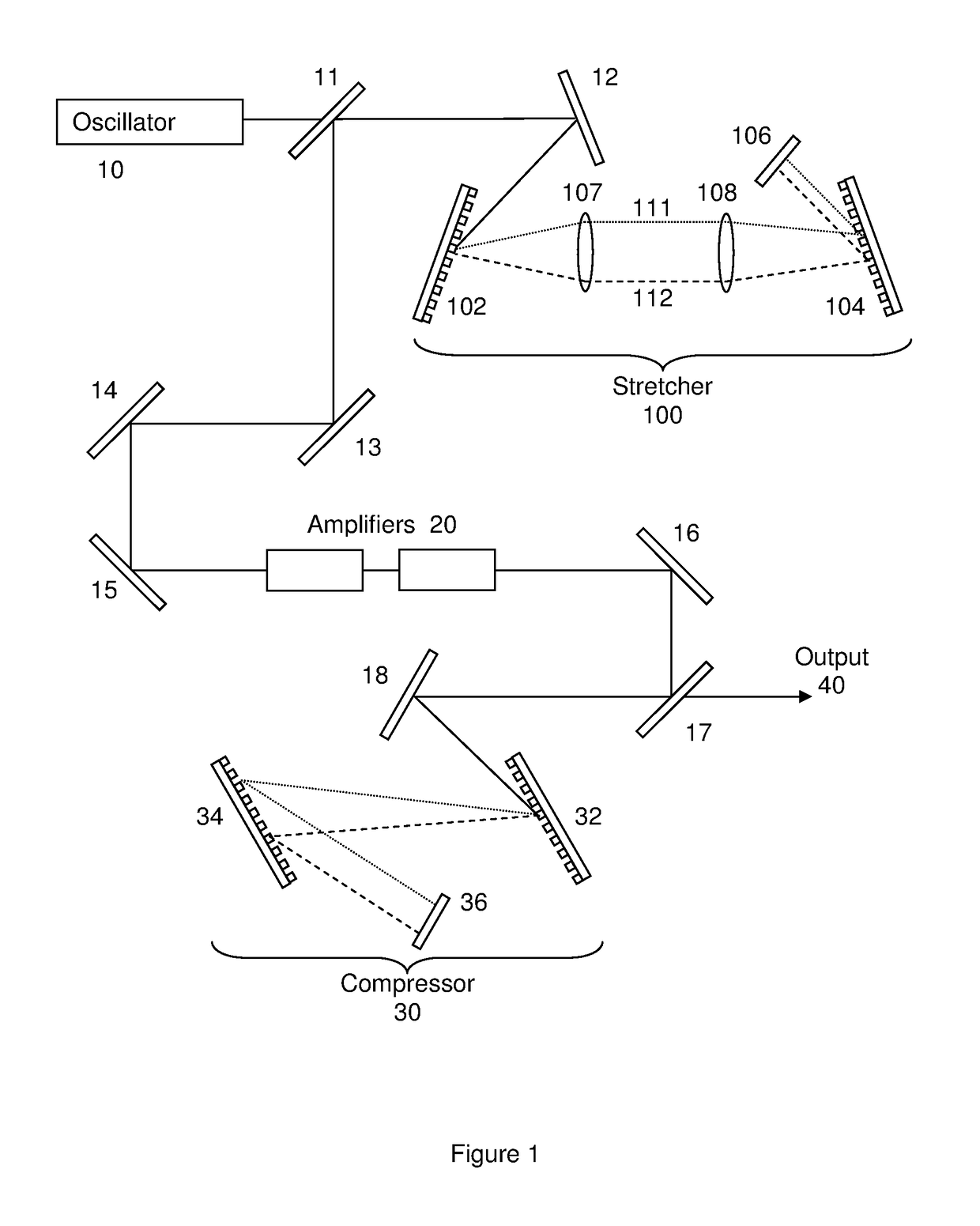
[0059]FIG. 1 is a schematic diagram of a high power chirped pulse amplification (CPA) laser system. The system consists of an oscillator 10, a pulse stretcher 100, an amplifier or multiple amplifiers 20 in a chain and a compressor 30. The oscillator provides a series of seed pulses for amplification. In the example of FIG. 1 the pulses are directed past mirror 11 and reflected at mirror 12 towards the stretcher 100. The mirror 11 is of limited size and at first pass from the oscillator to mirror 12, the pulses pass above or to the side of mirror 11 bypassing it. Alternatively, the mirror 11 may be a partially reflecting mirror such as a semi-silvered mirror. The stretcher comprises a pair of diffraction gratings 102 and 104, a pair of lenses 107 and 108, and back mirror 106. Mirror 12 directs the pulses at the first diffraction grating 102. The diffraction grating diffracts the input pulse according to their wavelength spreading the pulse such that the different wavelengths diverge ...


PUM


Abstract

A high power laser with chirped pulse amplification to produce extremely high power ultrashort pulses is disclosed. A pulse stretcher and methods of stretching a laser pulse are also disclosed. The pulse stretcher comprises: a first diffraction grating (G1) arranged to receive and disperse a seed laser pulse; transfer optics (CM) arranged to collect the dispersed pulse and direct it to a transmission diffraction grating (G2) which is either the first diffraction grating or a second diffraction grating; the transmission diffraction grating arranged to collimate the collected pulse to a reflector (BM), the reflector arranged such that the pulse is reflected back through the pulse stretcher via the transmission diffraction grating. The pulse stretcher provides better phase noise performance of the output pulse, and therefore a reduction in the noise floor to improve contrast pedestal.

Description

TECHNICAL FIELD[0001]The present invention relates to a high power laser with chirped pulse amplification to produce extremely high power ultrashort pulses. In particular, the present invention relates to improvements in the pulse stretcher to improve the temporal profile of the ultrashort pulses.BACKGROUND[0002]Recent advances in chirped pulse amplification (CPA) have allowed the realisation of extremely high power and high intensity laser pulse generation. Such pulses can have a power density as high as ˜1022 W / cm2 through the use of titanium:sapphire (Ti:Sa) amplifiers. Pulse durations can be of the order of 30 fs.[0003]Such ultra-high intensity lasers are a powerful and efficient drive source for accelerating electrons. They also find application in many other areas. However, their use in accelerating electrons is particularly suited to generating high energy electron beams (of the order of GeV), which can be used for generating ultrafast pulses of coherent X-rays. The ultra-hig...

Claims


Application Information

Patent Timeline
Patent Type & Authority Applications(United States)
IPC IPC(8): H01S3/00H01S3/23
CPCH01S3/2316H01S3/0057
Inventor HOOKER, CHRISTOPHER JOHNRAJEEV, PARAMEL PATTATHILTANG, YUNXIN
Owner UK RES & INNOVATION LTD
Why Eureka
Try Eureka