System and method for tuning a frequency generator using an LC oscillator

a frequency signal and oscillator technology, applied in oscillator generators, pulse automatic control, electrical equipment, etc., can solve the problems of limited performance, inaccurate, one-dimensional, and slow adjustment, and achieve accurate coarse tuning, small size, and better quality factor

Active Publication Date: 2009-03-31
GCT SEMICONDUCTOR INC
View PDF22 Cites 11 Cited by
  • Summary
  • Abstract
  • Description
  • Claims
  • Application Information

AI Technical Summary

Benefits of technology

[0015]Another object of the present invention is to control the output frequency of a phase-locked loop in a way that is faster than other methods which have been proposed.
[0020]Another object of the present invention is to achieve the aforementioned objects using one or more capacitive arrays that perform very accurate coarse tuning, which, in turn, allows the smaller-size varactors to be used for fine tuning.
[0021]Another object of the present invention is to provide a PLL which has improved phase noise performance compared with other circuits which have been proposed.
[0023]The present invention thus reduces the total bit-comparison time of a coarse tuning period. Also, the trade-off between coarse tuning time and the accuracy of coarse tuning may be optimally resolved by adopting a weighted comparison time for coarse tuning of each bit decision. The bit-comparison time for each coarse tuning bit can be set differently according to the comparison resolution.

Problems solved by technology

The FIG. 2 circuit has a number of drawbacks which limit performance.
For example, while the varactors may be used to adjust the output frequency of the VCO, the adjustments tend to be slow, inaccurate, and one-dimensional.

Method used


Image

  • System and method for tuning a frequency generator using an LC oscillator
  • System and method for tuning a frequency generator using an LC oscillator
  • System and method for tuning a frequency generator using an LC oscillator

Examples


Embodiment Construction

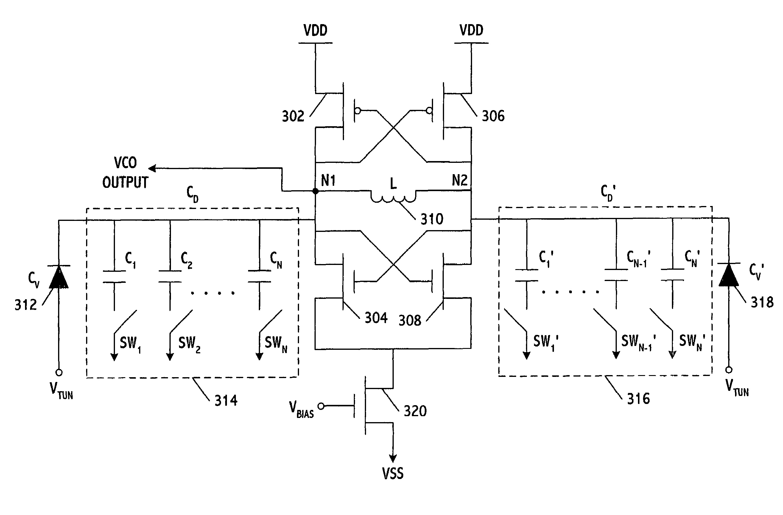
[0037]FIG. 3 shows an LC-VCO which includes two cross-coupled CMOS inverters, an inductor, and two capacitive circuits which are connected in parallel to the inductor. The first inverter is formed from PMOS transistor 302 and NMOS transistor 304, and the second inverter is formed from PMOS transistor 306 and NMOS transistor 308. The inverters are cross-coupled by connecting the common drain of the first inverter to the common gate of the second inverter and vice versa. The inverters thus form a multivibrator. The inductor 310 (L) is connected to the inverters and the capacitive circuits at nodes N1 and N2, either of which may be used to supply the output frequency of the VCO. For illustrative purposes, N1 is shown as supplying the output frequency.

[0038]The first capacitive circuit fine tunes the output frequency of the VCO using two analog varactors (Cv, Cv′) 312 and 318. The second capacitive circuit performs coarse tuning and includes two discrete capacitor arrays (CD, CD′) 314 a...


PUM


Abstract

An LC-VCO includes a multivibrator which outputs a frequency signal, a fine tuning circuit which tunes the frequency signal by a first amount, a coarse tuning circuit which tunes the frequency signal by a second amount, and a control circuit which controls the fine and coarse tuning circuits. The coarse tuning circuit is formed from one or more capacitive arrays and the fine tuning circuit is formed from one or more varactors. The capacitive arrays are preferably controlled by a digital signal, where each bit selectively couples a respective capacitor to the multivibrator. An analog signal controls the value of the varactors. The capacitive arrays and varactors charge and discharge an inducator in the multivibrator to tune the frequency signal. The VCO may be incorporated within a phase-locked loop, where the capacitors may be assigned different weight and / or redundancy values to tune an output frequency signal. In one embodiment, coarse tuning and lead-lag detection is performed more accurately to allow the size of the varactors to become significantly reduced compared with other circuits which have been proposed.

Description

CROSS-REFERENCE TO RELATED APPLICATIONS[0001]This application claims benefit to U.S. Provisional Patent Application Ser. No. 60 / 545,933, filed on Feb. 20, 2004, the contents of which are incorporated herein by reference.BACKGROUND OF THE INVENTION[0002]1. Field of the Invention[0003]The present invention generally relates to generating frequency signals, and more particularly to a system and method for controlling a frequency signal generator such as a phase lock loop.[0004]2. Background of the Related Art[0005]Phase locked loops (PLLs) are used in many wireless systems to perform digital clock synchronization, frequency synthesizing, and other functions. FIG. 1 shows a PLL which has been used in communication systems. This PLL includes a phase / frequency detector (PFD) 102, a charge pump and loop filter 104, a voltage-controlled oscillator (VCO) 106, and an optional frequency divider 108 situated along a feedback loop between the VCO and PFD.[0006]In operation, the PFD compares phas...

Claims


Application Information

Patent Timeline
Patent Type & Authority Patents(United States)
IPC IPC(8): H04B7/00H04B1/18H03B5/00H03L7/085H03L7/099H03L7/197H03L7/199
CPCH03L7/085H03L7/099H03L7/199H03L7/1976H04B1/06H04B7/00H03B5/00
Inventor LEE, KANG YOONKOO, YIDOLEE, JEONG-WOOPARK, JOONBAELEE, KYEONGHO
Owner GCT SEMICONDUCTOR INC
Why Eureka
Try Eureka