Micro valve, method for producing a micro valve, as well as micro pump

a technology of micro valves and valve bodies, which is applied in the direction of functional valve types, machines/engines, and positive displacement liquid engines, can solve the problem of only switching, and achieve the effect of expanding functionality and being easy to produ

Active Publication Date: 2010-10-21
ROBERT BOSCH GMBH
View PDF30 Cites 42 Cited by
  • Summary
  • Abstract
  • Description
  • Claims
  • Application Information

AI Technical Summary

Benefits of technology

[0003]Example embodiments of the present invention provide a micro valve that has an expanded functionality and is easy to produce. Furthermore, example embodiments provide a suitable production method and also a micro pump having such a micro valve.

Problems solved by technology

A disadvantage of a conventional micro valve is that it switches solely as a function of the pressure differential between the two valve chambers.

Method used


Image

  • Micro valve, method for producing a micro valve, as well as micro pump
  • Micro valve, method for producing a micro valve, as well as micro pump
  • Micro valve, method for producing a micro valve, as well as micro pump

Examples


Embodiment Construction

[0031]Identical components and components having the same function are labeled by the same reference symbols in the figures.

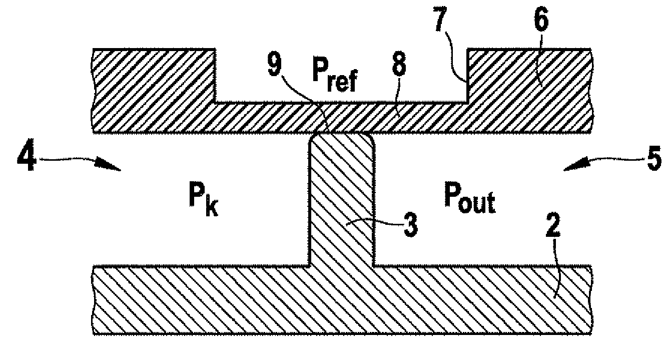
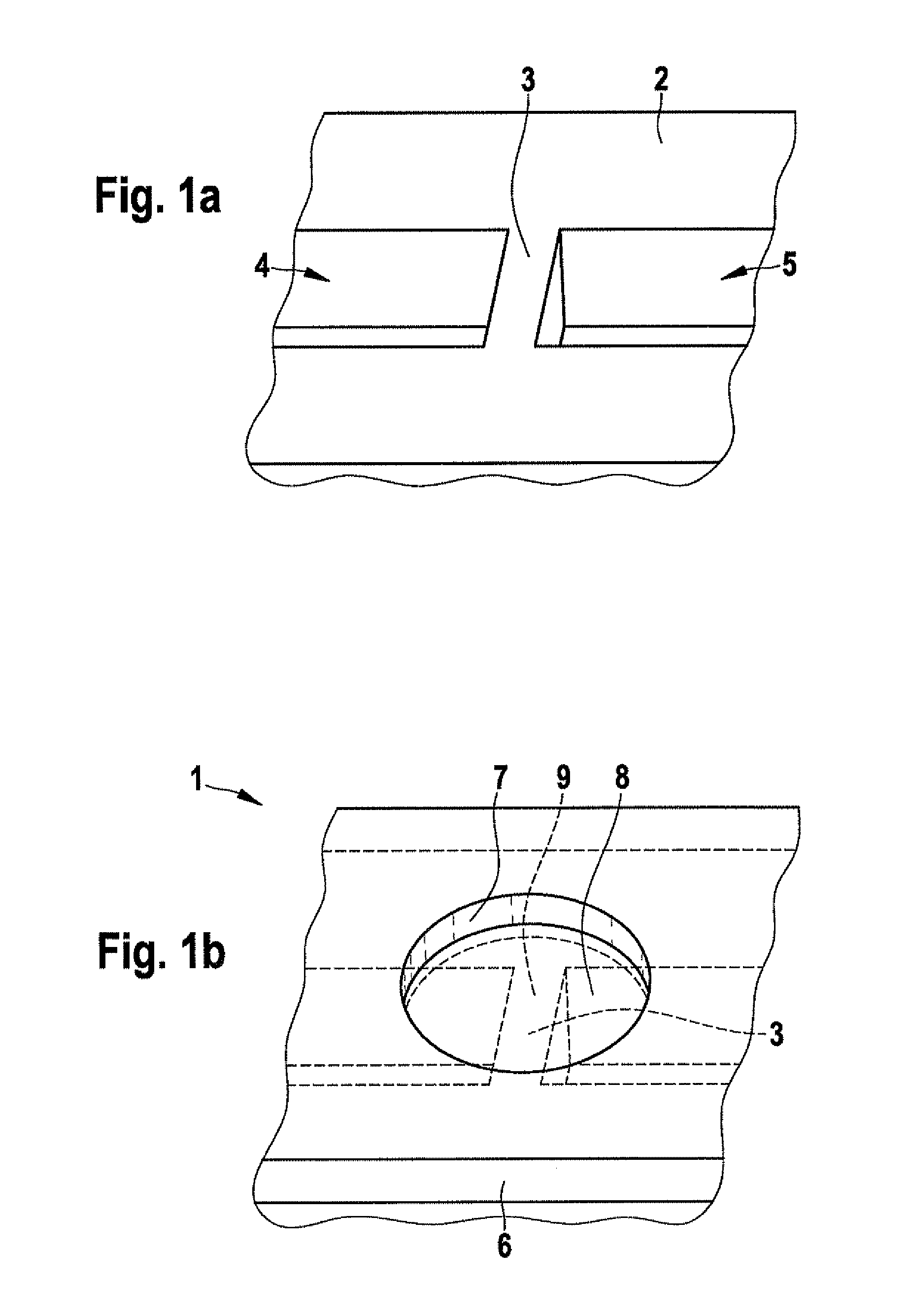
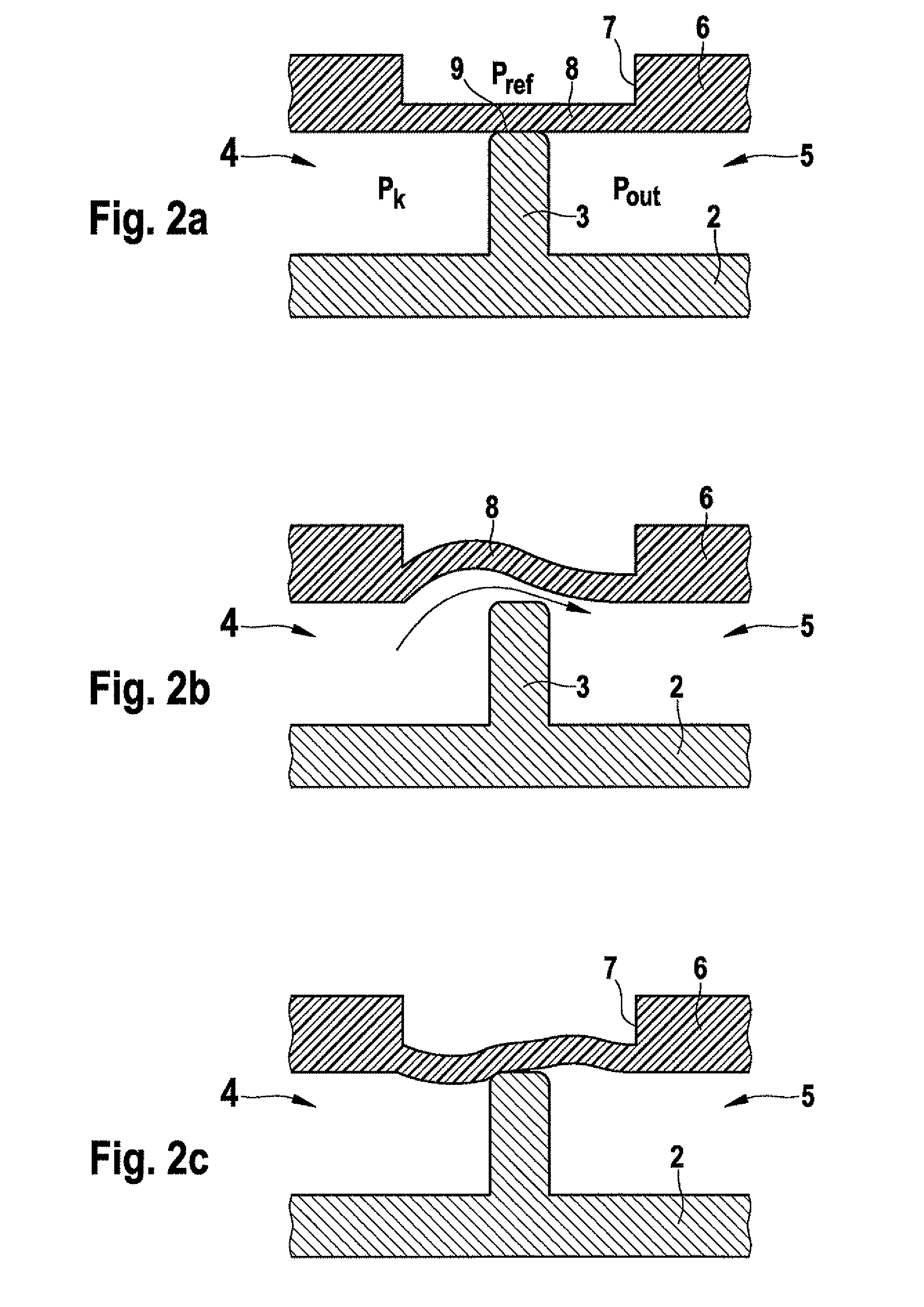
[0032]FIGS. 1a and 1b illustrate the basic structure of a micro valve 1. FIG. 1a shows a base plate 2 made of a semiconductor material, into which a channel or trench has been introduced, which is separated by a separation wall 3, the resulting channel sections forming a first and a second valve chamber. Separation wall 3 extends perpendicular to the longitudinal extension of the channel.

[0033]A functional layer 6 has been affixed on top of base plate 2, and a reference chamber 7 has been introduced in functional layer 6, which reference chamber may be connected to the environment at the upper side in the drawing plane, or which preferably may be sealed by an additional layer (plate). The bottom of reference chamber 7 contoured in the shape of a circular ring is formed by a closing element arranged as an elastic diaphragm, the closing element extending across b...


PUM

PropertyMeasurementUnit
pressureaaaaaaaaaa
vacuum pressureaaaaaaaaaa
semiconductoraaaaaaaaaa

Abstract

A micro valve includes a first valve chamber and a second valve chamber as well as a closing element, which is adjustable between an opening position, in which the valve chambers are connected to each other, and a closing position in which the valve chambers are separated from each other. A reference chamber is provided, which is delimited by the closing element.

Description

FIELD OF THE INVENTION[0001]The present invention relates to a micro valve, a method for producing a micro valve, and to a micro pump.BACKGROUND INFORMATION[0002]In micro-fluid technology, which provides new applications, e.g., in the pharmaceutical and medical field or in industrial processing engineering, elements for transporting and controlling the fluids are of particular importance. At present, the micro-valves used in micro pumps, in particular, are usually designed according to the dual-chamber principle, in which a closing element, which opens only at a particular pressure configuration as a function of the pressure differential between the two valve chambers, is situated between two valve chambers. Such a dual-chamber micro valve is described in DE 103 34 240. A disadvantage of a conventional micro valve is that it switches solely as a function of the pressure differential between the two valve chambers. Although a conventional micro valve is relatively easy to produce, th...

Claims


Application Information

Patent Timeline
Patent Type & Authority Applications(United States)
IPC IPC(8): F04B45/02B23P15/00
CPCY10T29/49236F16K99/0015F16K99/0057F16K99/0001F16K2099/0094F04B43/043F16K99/0059Y10T137/7779Y10T137/7837Y10T137/7879Y10T137/778F16K15/144
Inventor PIRK, TJALFSTUMBER, MICHAEL
Owner ROBERT BOSCH GMBH
Why Eureka
Try Eureka