Testing system and method for fan module

Inactive Publication Date: 2010-10-21
HONG FU JIN PRECISION IND (SHENZHEN) CO LTD +1
View PDF5 Cites 5 Cited by
  • Summary
  • Abstract
  • Description
  • Claims
  • Application Information

AI Technical Summary

Problems solved by technology

However, such a test method needs a server system with storage system, whic

Method used


Image

  • Testing system and method for fan module
  • Testing system and method for fan module
  • Testing system and method for fan module

Examples


Embodiment Construction

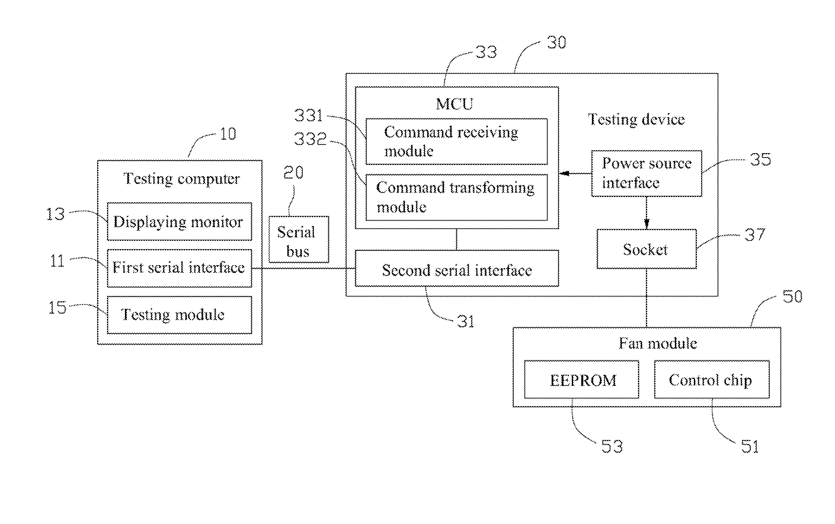
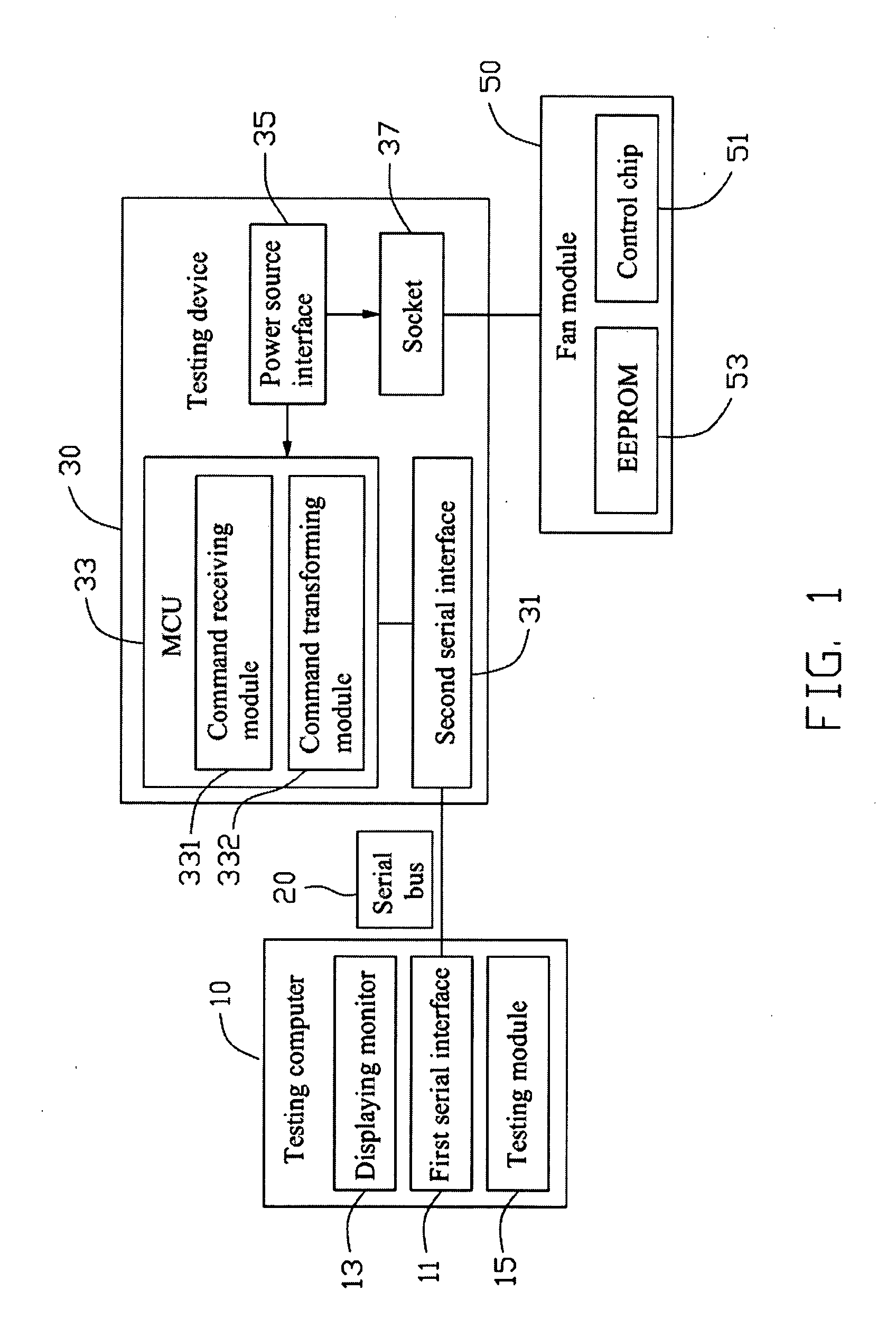
[0009]An embodiment of a testing method for testing a fan module 50 is provided. A testing system for performing the testing method includes a testing computer 10 and a testing device 30 connected to the testing computer 10. The fan module 50 is installed on the testing device 30.

[0010]The testing computer 10 includes a first serial interface 11 and a display monitor 13. A testing module 15 is disposed in the testing computer 10, and configured to analyze the information from the testing device 30. The display monitor 13 is used for showing test results.

[0011]The testing device 30 includes a second serial interface 31 corresponding to the first serial interface 11, a Micro Control Unit (MCU) 33, a power source interface 35, and a socket 37. A serial bus 20 connects the first serial interface 11 to the second serial interface 31, thereby establishing communication between the testing computer 10 and the testing device 30. A command receiving module 331 and a command transforming modu...


PUM


Abstract

A testing method for a fan module is provided. When the fan module is tested, a testing computer sends a testing command to a testing device first. Then, the testing device respond to the testing command and controls the fan module to work in a plurality of rotational speed modes in sequence. The testing device reads an actual rotational speed when the fan module works in one of the rotational speed modes and sends the actual rotational speed back to the testing computer. The testing computer compares the actual rotational speed with a corresponding reference rotational speed value stored in the testing computer, and determines the testing result. Finally, the testing result is shown.

Description

BACKGROUND[0001]1. Technical Field[0002]The present disclosure relates to testing systems and methods, and particularly, to a testing system and method for a fan module.[0003]2. Description of Related Art[0004]A fan module is an important component mounted in a computer system, and is used for removing heat generated by electronic components in the computer system. Generally, the fan module must be quality tested before the fan module enters into the market for use. Conventionally, the fan module is installed in a storage system assembled to a server system. When testing the fan module, the server system is started up to operate the fan module and initialize a test procedure to test the fan module. However, such a test method needs a server system with storage system, which increases test cost. Furthermore, such a test procedure is time consuming.BRIEF DESCRIPTION OF THE DRAWINGS[0005]Many aspects of the embodiments can be better understood with references to the following drawings....

Claims


Application Information

Patent Timeline
IPC IPC(8): G06F19/00G01P3/00
CPCF04D25/08F04D27/004F04D27/001Y02B30/70
Inventor CHOU, SHU-HSIENGUO, LI-WENTAN, BI-HUIWANG, KANG-BIN
Owner HONG FU JIN PRECISION IND (SHENZHEN) CO LTD
Why Eureka
Try Eureka