Device for blowing gas onto a face of a traveling strip of material

a technology of traveling strip and gas, which is applied in the direction of heat treatment apparatus, drying machines with progressive movement, furnaces, etc., can solve the problems of reducing affecting and affecting the efficiency of the blowing process, so as to minimize the vibration or offset of the strip, the effect of optimizing the thermal and air-flow aspects of the blowing

Inactive Publication Date: 2010-10-28
COCKERILL MAINTENANCE & INGIE
View PDF3 Cites 18 Cited by
  • Summary
  • Abstract
  • Description
  • Claims
  • Application Information

AI Technical Summary

Benefits of technology

[0012]The invention aims to provide a gas blower device that does not present the drawbacks and / or limitations of the above-mentioned prior art systems, and that optimizes both the thermal and air-flow aspects of blowing, while minimizing the vibration or offsets of the strip while it is traveling, and to do this with an installation of cost that is reasonable.

Problems solved by technology

In the above-mentioned devices, the orifices of the tubular nozzles are at a distance from the strip that is sufficient to avoid any risk of contact with said strip, which would risk marking the strip of material and damaging it, or possibly tearing off the tubular blower nozzles.
In order to improve cooling performance, it is necessary either to reduce said distance in substantial manner, or else to organize the blower system so as to have very high flow rates, which leads to high cost, or indeed to adopt both of the above-mentioned solutions, but that further increases the risk of contact between the strip and the blower nozzles because of the difficult-to-control oscillations of the strip while said strip is traveling.

Method used


Image

  • Device for blowing gas onto a face of a traveling strip of material
  • Device for blowing gas onto a face of a traveling strip of material
  • Device for blowing gas onto a face of a traveling strip of material

Examples


Embodiment Construction

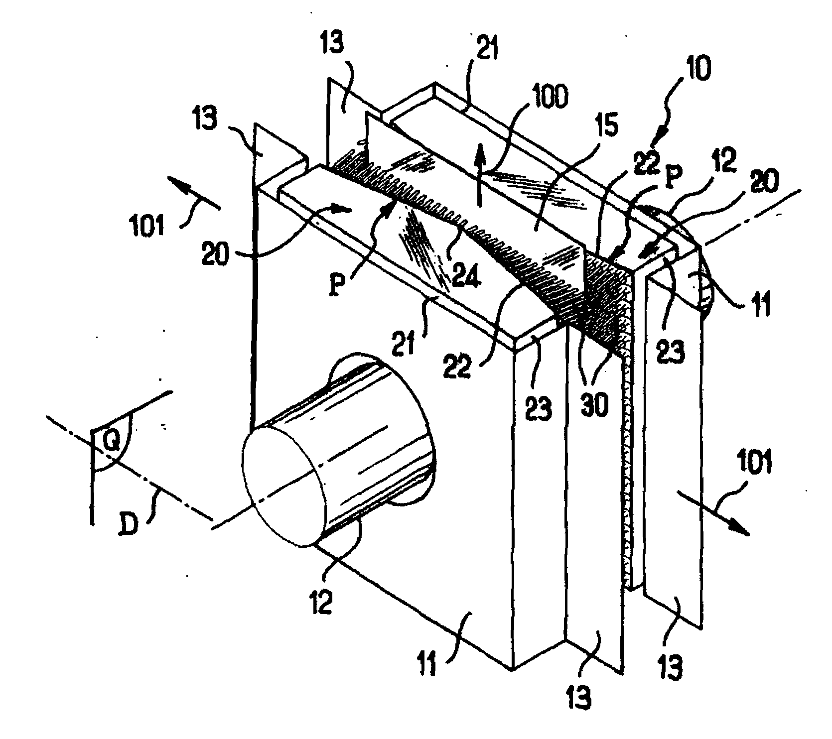
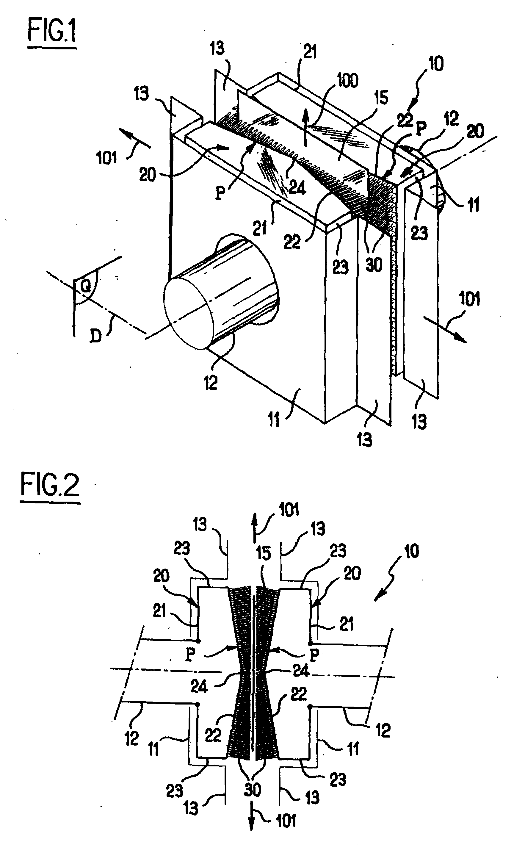
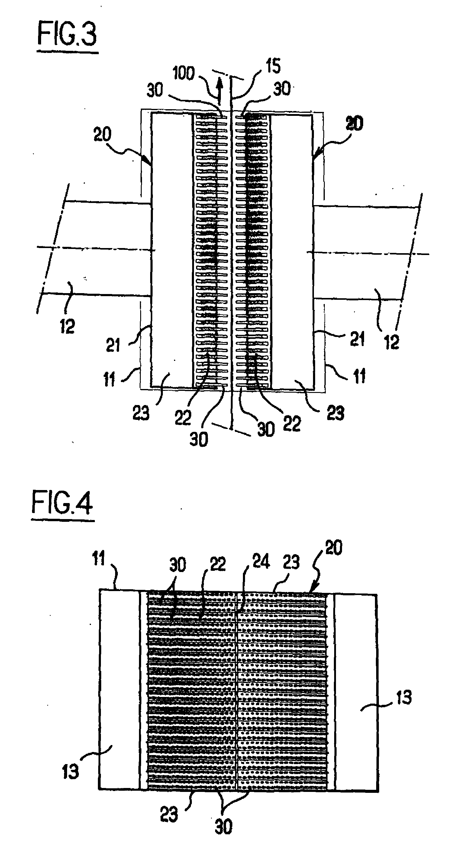
[0034]FIGS. 1 to 3 show a portion of a blower installation including a gas blower device in accordance with the invention and given reference 10.

[0035]On either side of a traveling strip of material given reference 15, and having a travel direction symbolized by arrow 100, the device 10 comprises structural elements 11, in this embodiment of an omega shape, with margins given reference 13, which elements are fastened to respective hollow boxes 20, the strip 15 of material traveling between the two facing hollow boxes.

[0036]Each hollow box 20 has two side faces 23, a back face 21 connected to a blowing gas admission tube 12 and a front or active surface 22, opposite from the face 21, which front surface is turned towards the face in question of the strip of material 15.

[0037]Each hollow box 20 is fitted with a plurality of tubular nozzles 30 pointing towards the face in question of the strip of material 15.

[0038]In accordance with a characteristic of the invention, the surface 22 of ...


PUM

PropertyMeasurementUnit
angleaaaaaaaaaa
distanceaaaaaaaaaa
angleaaaaaaaaaa

Abstract

A gas blower device for blowing gas onto a face of a traveling strip of material. The device has at least one hollow box fitted with a plurality of tubular nozzles pointing towards the face in question of the strip of material. On the side facing towards the face in question of the strip of material, the hollow box presents a surface of profile (P) that varies in at least one given direction (D) symmetrically about a midplane (Q) perpendicular to the plane of the strip. The tubular nozzles are fastened via their roots to the varying-profile surface in such a manner that their respective axes are essentially orthogonal to said varying profile at the point in question, said tubular nozzles having respective lengths that are selected so that the outlet orifices lie in a common plane substantially parallel to the plane of the strip.

Description

[0001]The present invention relates to a gas blower device for blowing gas onto a surface of a traveling strip of material. The invention relates particularly to processing lines for processing strips of steel or aluminum by using at least one cooling chamber for cooling by means of gas jets, or one cooling section for cooling by means of gas jets, such as thermal processing lines, in particular continuous annealing lines, or such as coating lines, in particular galvanization lines.[0002]However, the invention is not limited to the above-mentioned field of use and relates more generally to blowing gas onto a face of a traveling strip of material that may be a non-metallic material, e.g. paper, or a plastics material, with a view to a drying, cooling, or coating, depending on the circumstances.BACKGROUND OF THE INVENTION[0003]For a long time it has been known to use gas blower devices for blowing gas onto one or two faces of a traveling strip of metal, in particular with a view to co...

Claims


Application Information

Patent Timeline
Patent Type & Authority Applications(United States)
IPC IPC(8): F26B19/00
CPCB21B45/0209C21D1/613C21D1/667C21D9/46F26B21/004C21D9/5735C21D9/63F26B13/10C21D9/573
Inventor LANGEVIN, STEPHANEDUBOIS, PATRICK
Owner COCKERILL MAINTENANCE & INGIE
Why Eureka
Try Eureka