Control system to manage and optimize a geothermal electric generation system from one or more wells that individually produce heat

a control system and geothermal technology, applied in mechanical equipment, machines/engines, light and heating equipment, etc., can solve problems such as environmental problems, abandoned, and large cost of wells created

Inactive Publication Date: 2010-10-28
PARDEV
View PDF52 Cites 27 Cited by
  • Summary
  • Abstract
  • Description
  • Claims
  • Application Information

AI Technical Summary

Benefits of technology

[0016]Wells that have been drilled for oil and gas exploration that are either depleted, or have never produced oil or gas, can now be used to generate electricity. A well can also be drilled specifically for the purpose of generating electricity. The only requirement is that the well is deep enough to generate heat from the bottom of th

Problems solved by technology

Wells that have been drilled for oil and gas exploration that are either depleted, or have never produced oil or gas, usually remain abandoned and/or unused and may eventually be filled.
Such wells were created at a large cost and create an environmental issue when no longer needed for their initial use.
While there are known geothermal heat/electrical methods and systems for using the geothermal heat/energy from deep within a well (in order to produce a heated fluid (liquid or gas) and generate electricity therefrom), these methods have significant environmental drawbacks and are usually inefficient in oil and gas wells due to the depth of such wells.
The water used for these systems is extremely harmful to the environment, as it is full of minerals, is caustic and can pollute water aquifers.
In the case of EGS systems, water injected into a well permeates the Earth as it travels over rock and other material under the Earth's surface, becoming polluted, caustic, and dangerous.
A water-based system for generating heat from a well presents significant and specific issues.
For example, extremely large quantities of water are often injected into a well.
This water becomes polluted with minerals and other harmful substances, often is very caustic, and causes problems such as seismic instability and disturbance of natural hydrothermal manifestations.
Additionally, there is a high potential for pollution of surrounding aquifers.
This polluted water causes additio

Method used


Image

  • Control system to manage and optimize a geothermal electric generation system from one or more wells that individually produce heat
  • Control system to manage and optimize a geothermal electric generation system from one or more wells that individually produce heat
  • Control system to manage and optimize a geothermal electric generation system from one or more wells that individually produce heat

Examples


Embodiment Construction

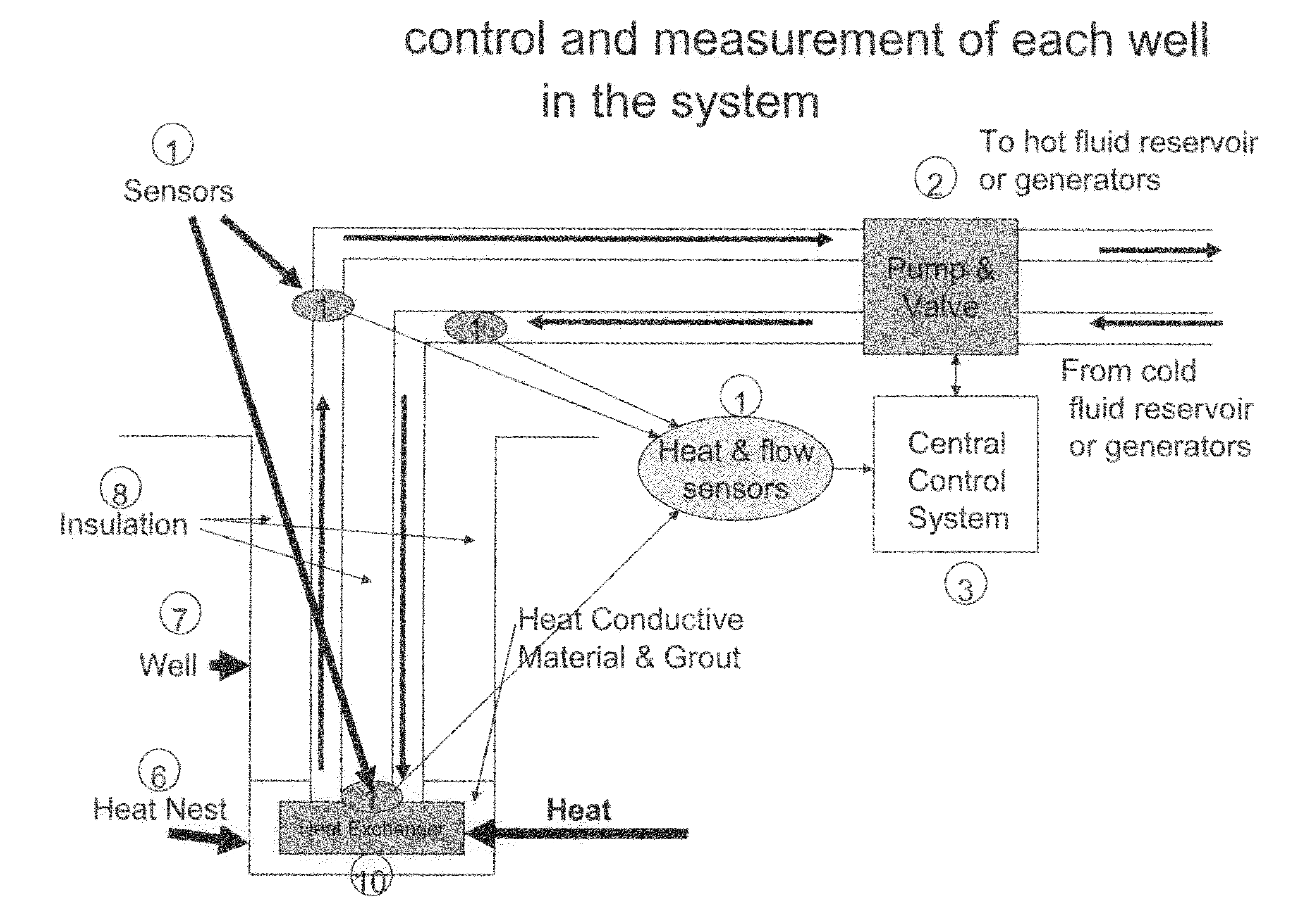
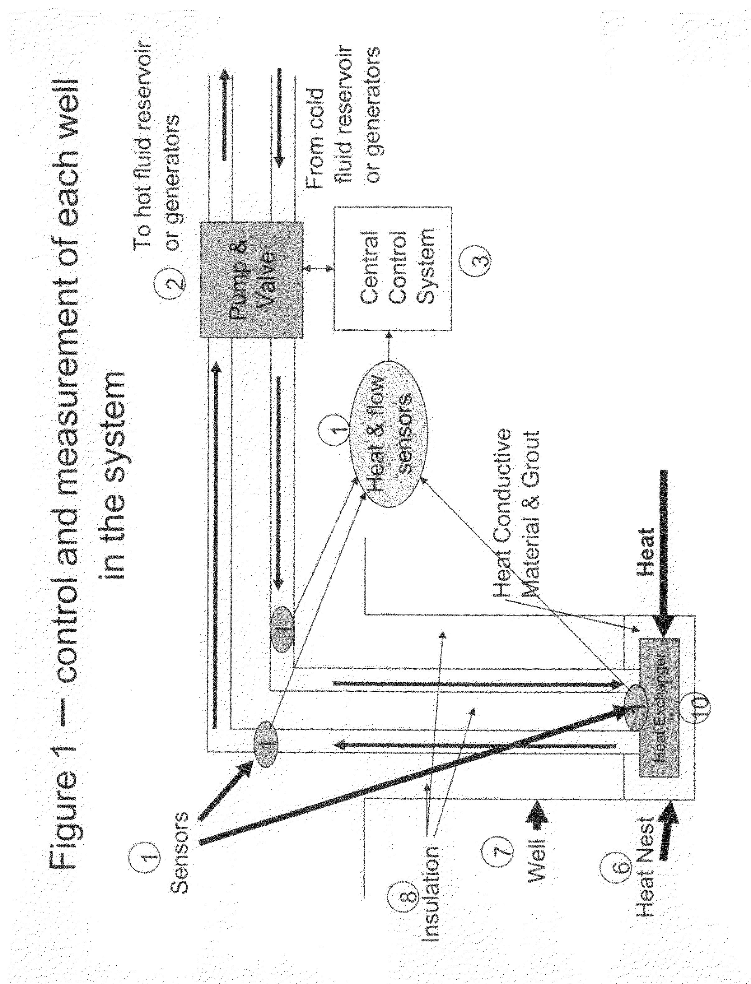
[0023]In the following description of the present invention reference is made to the accompanying drawings which form a part thereof, and in which is shown, by way of illustration, exemplary embodiments illustrating the principles of the present invention and how it may be practiced. It is to be understood that other embodiments may be utilized to practice the present invention and structural and functional changes may be made thereto without departing from the scope of the present invention.

[0024]FIG. 1 illustrates a first preferred embodiment of the control system for a single well system7 of the present invention, wherein said system is comprised of a single closed loop having a heat harnessing component and an electricity generating component. Fluid is pumped 2 down the well in a closed loop to a heat nest that contains a heat exchanger. The heat exchanger transfers the heat at the bottom of the well tot the fluid. The fluid carries the heat to the surface and then to a hot flui...


PUM


Abstract

A control system manages and optimizes a geothermal electric generation system from one or more wells that individually produce heat. The control system includes heat sensors that measure temperature and fluid flow and are placed at critical points in the wells, in piping, in a hot fluid reservoir, in a cold fluid reservoir and in a cooling system. The control system also includes pump and valve controls, generator controls, a network for gathering information and delivering instructions, and a processing module that collects information and communicates control information to each component.

Description

CROSS REFERENCE TO RELATED APPLICATIONS[0001]This application is a continuation-in-part of United States Non-Provisional patent application Ser. No. 12 / 456,434 filed on Jun. 15, 2009. This application also claims priority to 1) U.S. Provisional Application No. 61 / 137,956, filed on Aug. 5, 2008; 2) U.S. Provisional Application No. 61 / 137,974, filed on Aug. 5, 2008; 3) U.S. Provisional Application No. 61 / 137,955, filed on Aug. 5, 2008; and 4) U.S. Provisional Application No. 61 / 137,975, filed on Aug. 5, 2008, the contents of all of which are hereby incorporated in their entirety.[0002]Design and control system to manage and optimize a geothermal electric generation system from one or more wells that individually produce heat.STATEMENT REGARDING FEDERALLY-SPONSORED RESEARCH OR DEVELOPMENT[0003]Not applicable.REFERENCE TO SEQUENCE LISTING, A TABLE, OR A COMPUTER PROGRAM LISTING COMPACT DISK APPENDIX[0004]Not applicable.BACKGROUND OF THE INVENTION[0005]The present invention relates gener...

Claims


Application Information

Patent Timeline
IPC IPC(8): F03G4/00
CPCF24J3/082F24J3/086F28F2013/006Y02E10/125Y02E10/16F24J2003/089F24T10/13F24T10/30F24T2010/56Y02E10/10
Inventor PARRELLA, MICHAEL J.
Owner PARDEV
Why Eureka
Try Eureka