This helps you quickly interpret patents by identifying the three key elements:
Problems solved by technology
Method used
Benefits of technology
Benefits of technology
[0019]According to the present invention, because the combustion burner includes the cooling unit that cools the part of the swirler vane surface on which the liquid fuel hits, it is possible to prevent the part of the swirler vane surface on which the liquid fuel hits from being heated up, to prevent formation of carbon deposit.
[0020]Furthermore, because the combustion burner includes, as the cooling unit, a multi-purpose injecting hole arranged on the vane pressure surface of the swirler vane for injecting a gas fuel during gas combustion, and injecting water during'liquid fuel combustion to the vane pressure surface of the swirler vane, a water film can be formed on the vane surface on the vane pressure surface to cool the part of the vane surface on which the liquid fuel hits. In this manner, a combustion temperature can be reduced, and formation of carbon deposit can be prevented. Furthermore, NOx in the combustion field can also be reduced.
[0021]Furthermore, because the combustion burner includes, as the cooling unit, the water injecting hole that is arranged upstream of the liquid fuel injecting hole provided on the fuel nozzle and in line therewith, and from which water is injected to the vane pressure surface of the swirler vane, a water film can be formed on the vane pressure surface of the swirler vane to cool the part of the swirler vane surface on which the liquid fuel hits. In this manner, a combustion temperature can be reduced, and formation of carbon deposit can be prevented.
[0022]Furthermore; because the combustion burner includes the cooling unit that injects mixed fuel prepared by mixing water and the liquid fuel evenly through the liquid fuel injecting hole to the vane pressure surface of the swirler vane, the water becomes vaporized first to reduce the combustion temperature, and to deprive temperature from the surface of the swirler vane. Therefore, formation of carbon deposit can be prevented.
[0023]Furthermore, because the combustion burner includes, as the cooling unit, the water cooling circuit formed inside the swirler vane, the temperature on the surface of the swirler vane can be reduced, to cool the part of the vane surface on which the liquid fuel hits, and to suppress the swirler vane from being heated up. In this manner, formation of carbon deposit can be prevented more effectively.
[0024]Furthermore, because the combustion burner includes, as the cooling units, the liquid fuel injecting hole arranged on the vane pressure surface of the swirler vane, and a water injecting hole that is arranged upstream of the liquid fuel injecting hole that is arranged on the vane pressure surface of the swirler vane to inject water to the vane pressure surface of the swirler vane, a water film can be formed on the vane pressure surface of the swirler vane to reduce the temperature of the vane pressure surface of the swirler vane. In this manner, formation of carbon deposit can be prevented.
Problems solved by technology
However, the conventional combustion burner 100A, such as the one shown in FIG. 8, has been limited in its capability to atomize the liquid fuel.
Furthermore, it has been extremely difficult to make the fuel density uniform in the fuel nozzle 110.
Method used
Image
Click on the blue label to locate the original text in one second.
Reading with bidirectional positioning of images and text.
Examples
first embodiment
[0066]A combustion burner according to a first embodiment of the present invention will now be explained with reference to some of the attached drawings.
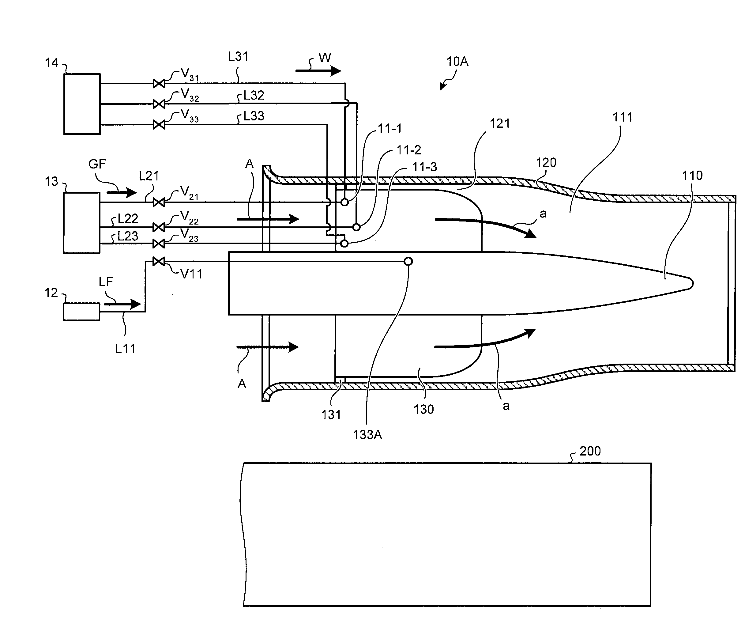
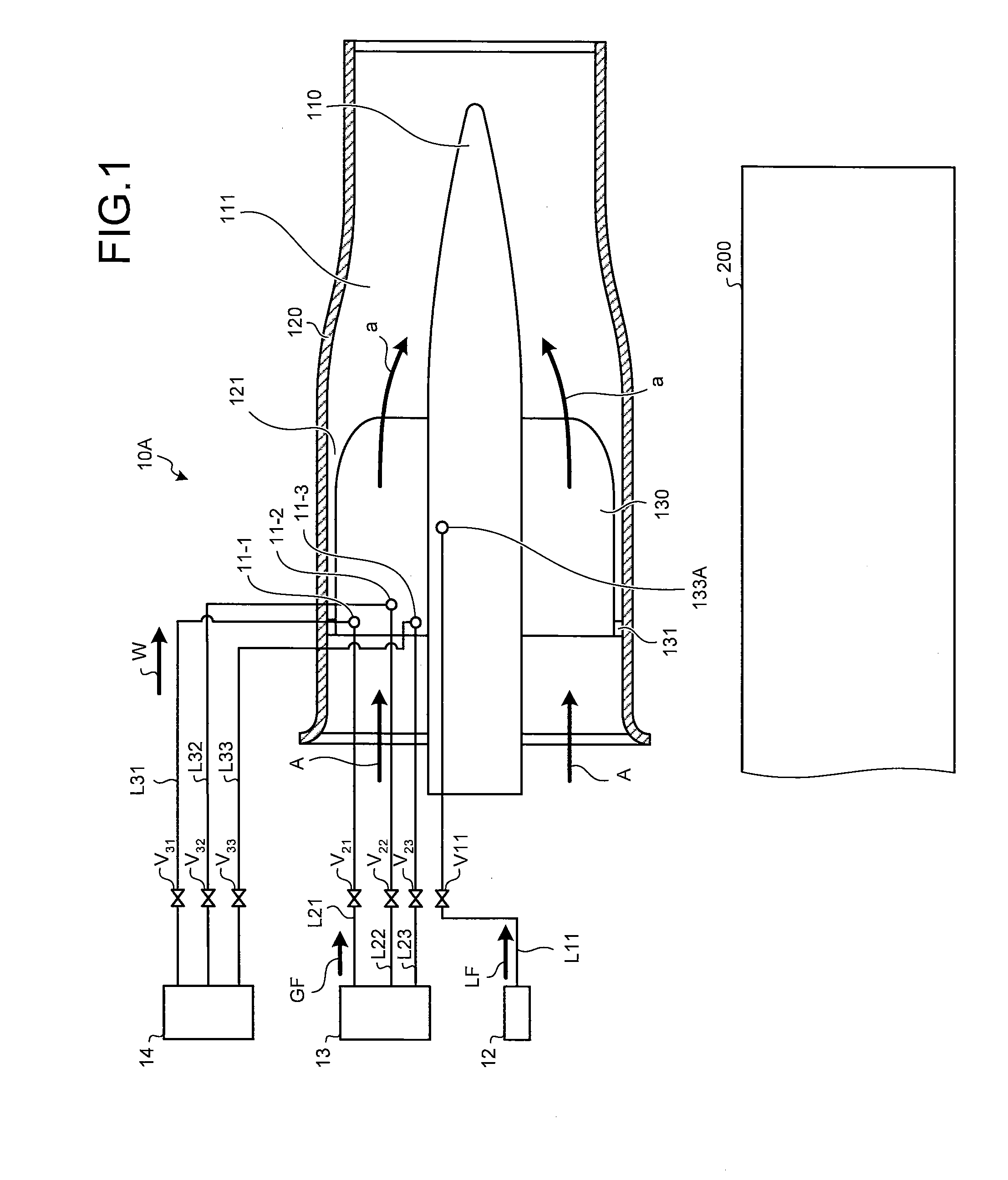
[0067]FIG. 1 is a schematic of a structure of the combustion burner according to the first embodiment of the present invention.
[0068]In FIG. 1, elements that are the same as those shown in FIGS. 8 to 10 are given the same reference numerals, and redundant explanations thereof are omitted.
[0069]As shown in FIG. 1, a combustion burner 10A according to the present embodiment includes: the fuel nozzle 110; the burner tube 120 surrounding the fuel nozzle 110 to form the air passage 111 between the burner tube 120 and the fuel nozzle 110; the swirler vanes (swirler vanes) 130 arranged in a plurality of positions in the circumferential direction on the external circumferential surface of the fuel nozzle 110, each extending along the axial direction of the fuel nozzle 110, and gradually curving from upstream to downstream of an air that flo...
second embodiment
[0098]A combustion burner according to a second embodiment of the present invention will now be explained with reference to FIG. 4.
[0099]The combustion burner according to the present embodiment has almost the same structure as that of the combustion burner 10A according to the first embodiment shown in FIG. 1; therefore, the same reference numerals are given to the elements that are same as those in the combustion burner 10A shown in FIG. 1, and redundant explanations thereof are omitted.
[0100]In the present embodiment, only the combustion nozzle 110 and the swirler vanes 130 are described and the other elements are omitted. The same can be said in the remaining embodiments.
[0101]FIG. 4 is a schematic of a structure of the combustion burner according to the second embodiment of the present invention.
[0102]As shown in FIG. 4, in a combustion burner 10B according to the present embodiment, the multi-purpose injecting holes 11-1 to 11-3, which are arranged on the vane pressure surface...
third embodiment
[0107]A combustion burner according to a third embodiment of the present invention will now be explained with reference to FIG. 5.
[0108]The combustion burner according to the present embodiment has almost the same structure as that of as the combustion burner 10A according to the first embodiment shown in FIG. 1; therefore, the same reference numerals are given to the elements that are same as those in the combustion burner 10A shown in FIG. 1, and redundant explanations thereof are omitted.
[0109]In the third embodiment, only the combustion nozzle 110 and the swirler vanes 130 are described, and the other elements are omitted.
[0110]FIG. 5 is a schematic of a structure of the combustion burner according to the third embodiment of the present invention.
[0111]As shown in FIG. 5, in a combustion burner 10C according to the present embodiment, the multi-purpose injecting holes 11-1 to 11-3, which are arranged on the vane pressure surface 132a of the swirler vanes 130 in the combustion bu...
PUM
Abstract
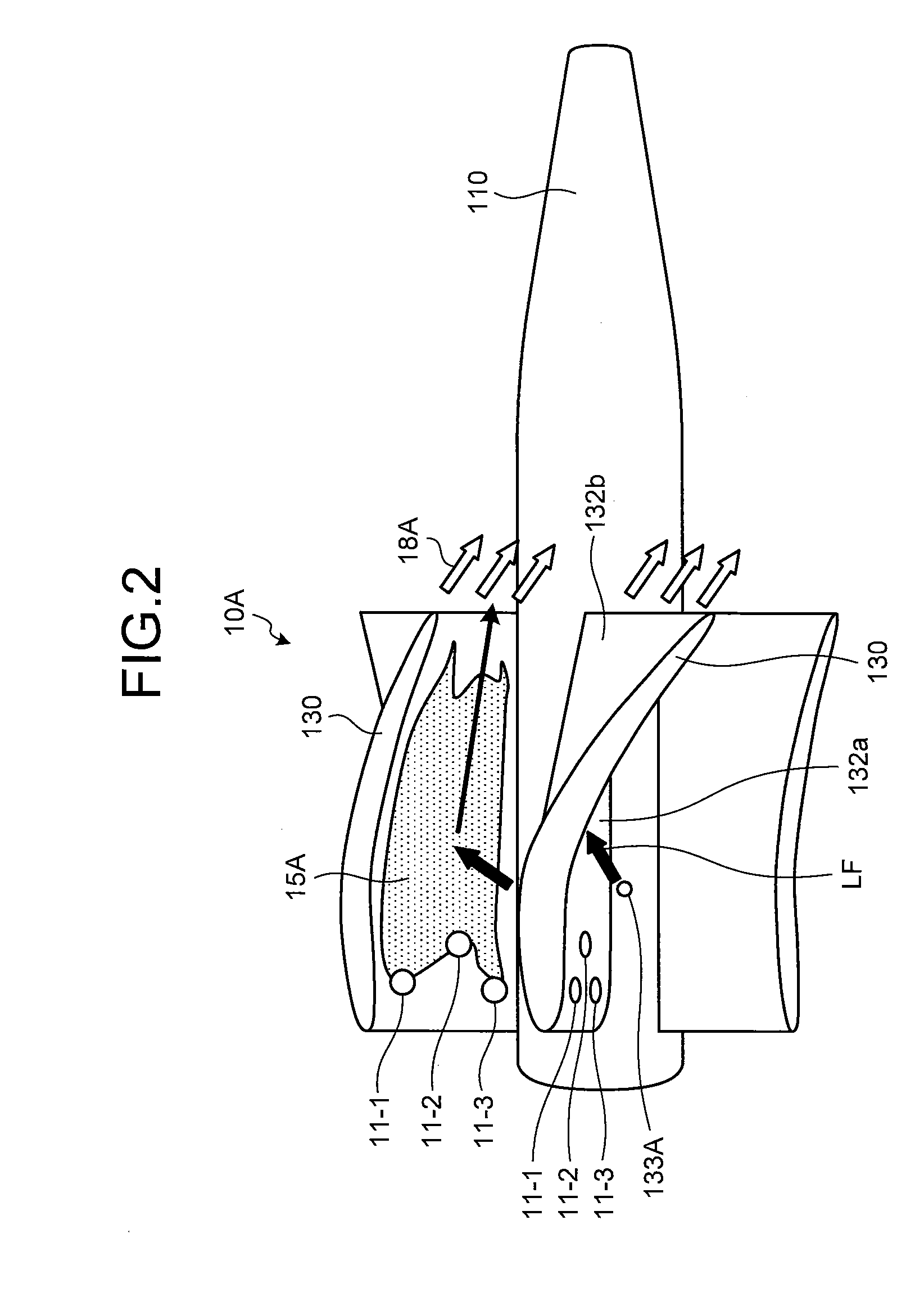
A combustion burner 10A according to one embodiment of the present invention includes: a fuel nozzle 110; a burner tube 120 forming the air passage 111 between the burner tube 120 and the fuel nozzle 110; swirler vanes (swirler vanes) 130 arranged in a plurality of positions in the circumferential direction on the external circumferential surface of the fuel nozzle 110, each extending along the axial direction of the fuel nozzle 110, and gradually curving from upstream toward downstream; and a liquid fuel injecting hole 133A from which a liquid fuel is injected to a surface of each of the swirler vanes 130. The combustion burner 10A also includes multi-purpose injecting holes 11-1 to 11-3 as a cooling unit that cools a part of a vane pressure surface 132a of the swirler vane 130 on which the liquid fuel LF hits. Water is injected through the multi-purpose injecting holes 11-1 to 11-3 to form a water film 15A on the vane pressure surface 132a, whereby a combustion temperature is reduced and formation of carbon deposit is prevented.
Description
TECHNICAL FIELD[0001]The present invention relates to a combustion burner that uses either only a liquid fuel, or both of a liquid fuel and a gas fuel, as a fuel.BACKGROUND ART[0002]A gas turbine, such as one used for generating power, includes, as its main components, a compressor, a combustor, and a turbine. Many gas turbines have a plurality of combustors, and the combustors included in the gas turbine are arranged in a circle in a combustor casing. Air compressed by the compressor is mixed with fuel supplied into the combustors, and is combusted. Such combustion takes place in each of the combustors to generate high temperature combustion gas. The combustion gas, produced by the combustion, is supplied to the turbine to drive the turbine in rotation.[0003]FIG. 8 indicates an exemplary structure of a combustion burner included in a combustor of a conventional gas turbine. As shown in FIG. 8, this combustion burner 100A is arranged in plurality (in FIG. 8, only one is depicted), s...
Claims
Application Information
Patent Timeline
Application Date:The date an application was filed.
Publication Date:The date a patent or application was officially published.
First Publication Date:The earliest publication date of a patent with the same application number.
Issue Date:Publication date of the patent grant document.
PCT Entry Date:The Entry date of PCT National Phase.
Estimated Expiry Date:The statutory expiry date of a patent right according to the Patent Law, and it is the longest term of protection that the patent right can achieve without the termination of the patent right due to other reasons(Term extension factor has been taken into account ).
Invalid Date:Actual expiry date is based on effective date or publication date of legal transaction data of invalid patent.

