
Integrated Solar Energy Conversion System, Method, and Apparatus

a solar energy and conversion system technology, applied in the field of solar energy harvesting, can solve the problems of solar energy conversion system that exceeds the performance of present solar energy conversion systems, and achieve the effect of high economic return on investment and high efficiency

Active Publication Date: 2010-10-28
LOCKHEED MARTIN CORP
View PDF6 Cites 0 Cited by
  • Summary
  • Abstract
  • Description
  • Claims
  • Application Information

AI Technical Summary

Benefits of technology

The integrated system achieves higher electrical energy production than previous systems, remaining within engineering parameters and optimizing output for the local environment, with theoretical efficiencies exceeding 60% and a high economic return on investment.

Problems solved by technology

Integrating all three types of these solar conversion techniques in a concentrated configuration produces a synergistic system that exceeds the performance of present solar conversion systems.

Method used


Image

  • Integrated Solar Energy Conversion System, Method, and Apparatus
  • Integrated Solar Energy Conversion System, Method, and Apparatus
  • Integrated Solar Energy Conversion System, Method, and Apparatus

Examples


Embodiment Construction

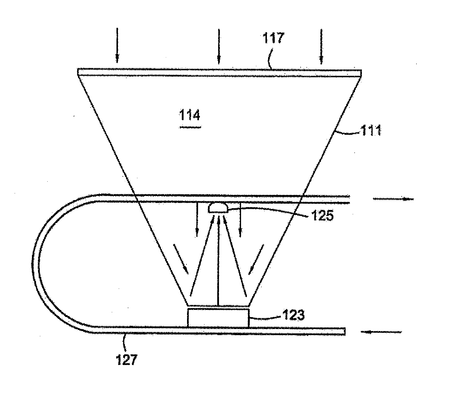
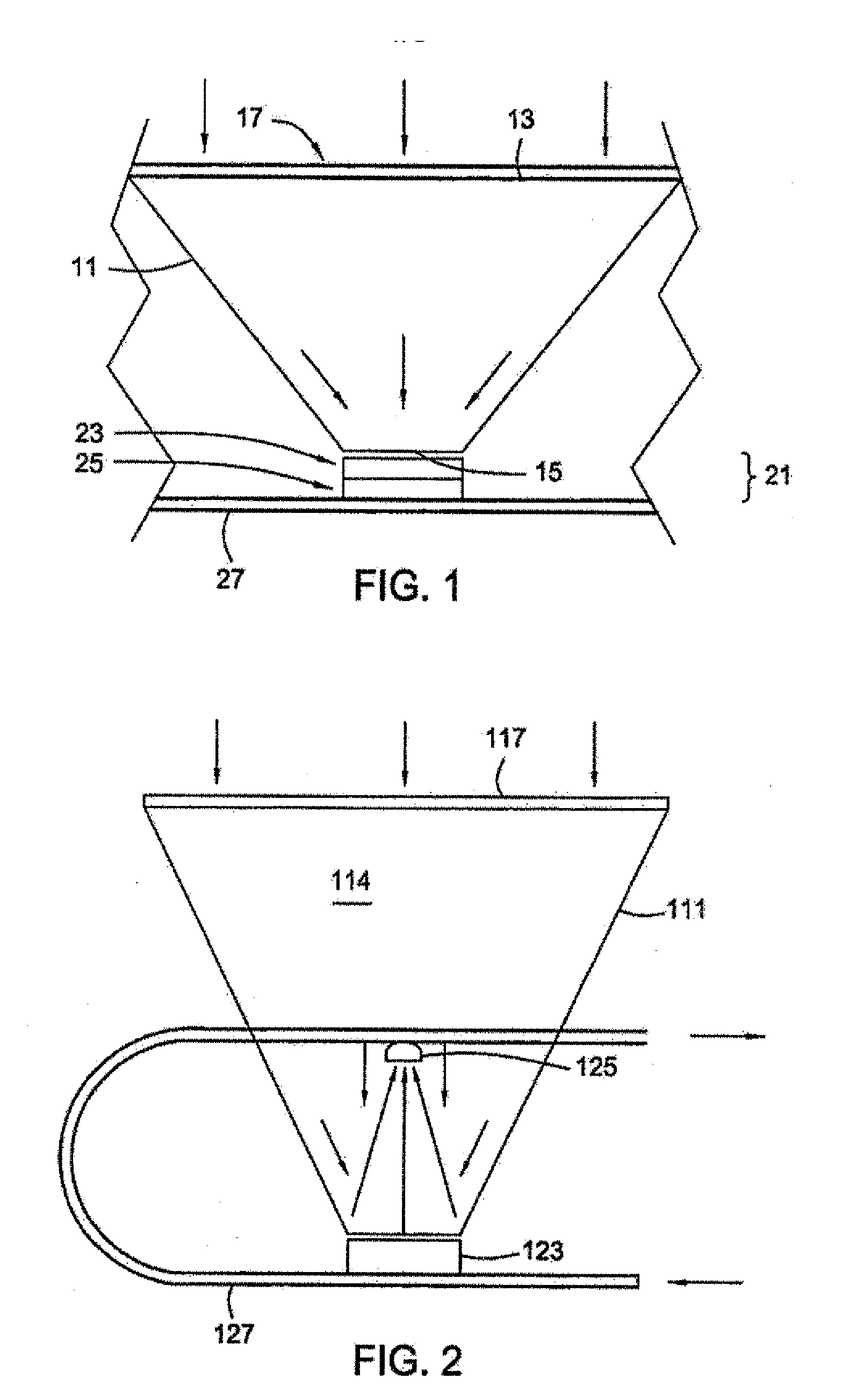
[0019]Referring to FIG. 1, one embodiment of a system and apparatus for solar energy conversion constructed in accordance with the present invention is shown. The invention comprises a housing 11 that controls optical orientation and spacing. Housing 11 may be a conical or parabolic reflective surface, or still other shapes such as those known in the art (e.g., round, linear, square, hexagonal, etc. reflectors). Housing 11 has an upper opening 13 and a lower opening or aperture 15 located opposite the upper opening 13. One or more cover lenses 17 (e.g., a fresnel, convex, etc. lens) is positioned adjacent the upper opening 13 of the housing 11 for concentrating solar energy toward the lower opening 15 of the housing 11.

[0020]A package 21 for converting solar energy is positioned adjacent the lower opening 15 of the housing 11 opposite the cover lens 17. In one embodiment, the package 21 comprises a photovoltaic (PV) cell 23 for converting solar energy into electrical power, a thermi...


PUM


Abstract

A solar energy conversion package includes a photovoltaic (PV) cell, a thermionic or thermoelectric conversion unit and a thermal heating system. Solar radiation is concentrated by a lens or reflector and directed to the PV cell for electrical power conversion. A water circulation system maintains the PV cell at working temperatures. The thermionic or thermoelectric conversion cell is coupled between these cells in the thermal path to generate additional power. Additional efficiencies may be gained by partitioning the solar radiation with prisms or wavelength specific filters or reflective coatings into discrete spectrum segments optimized for each conversion unit for maximizing efficiency of electrical energy conversion and equipment design. Integrating all three of these conversion techniques produces a synergistic system that exceeds the performance conventional solar conversion systems.

Description

BACKGROUND OF THE INVENTION[0001]1. Technical Field[0002]The present invention relates in general to harnessing solar energy and, in particular, to an improved system, method, and apparatus for integrating the conversion of solar energy into a variety of usable energy forms.[0003]2. Description of the Related Art[0004]In the prior art, solar energy conversion systems attempt to use a single energy conversion mechanism to achieve an efficiency that would make them economically feasible. Reaching a sufficiently high rate of power conversion for broad-based economic viability is difficult if not impossible at present and has restrained the growth of the solar energy industry.[0005]For example, one national solar power program achieved about 34% electric conversion efficiency at 660 suns concentration. Despite the high conversion compared with the commercial state of the art, this system's single conversion process only utilized a portion of the spectrum efficiently. However, that solut...

Claims


Application Information

Patent Timeline
Patent Type & Authority Applications(United States)
IPC IPC(8): H01L35/02H01L31/0216H10N10/80H10N10/13
CPCF24J2/062F24J2/08F24J2/10H01L31/055H02S10/10Y02E10/52Y02E10/60H01L31/0543H02S40/44H01L35/30Y02E10/44F24S23/00F24S23/70F24S23/30F24S23/10F24S50/20H10N10/13
Inventor HECHT, DANIEL H.
Owner LOCKHEED MARTIN CORP
Learn More